![]()
![]()
![]()
![]()
![]()
![]()
![]()
![]()
![]()
![]()
![]()
![]()
![]()
![]()
![]()
![]()
![]()
![]()
![]()
![]()
![]()
![]()
![]()
![]()
![]()
![]()
![]()
![]()
![]()
![]()
EMI and RFI Field Effects
The Kenwood L-07D offers a host of performance features. The deck offers world-class performance in the areas of speed accuracy, absolute speed stability, high transient load characteristics, high rigidity, anti-vibration properties and tonearm quality. So is this the "perfect deck"? Did the Kenwood engineers "get it right" on every single design issue? The answer to both questions is no. The L-07D has a significant flaw that was not adequately corrected by the original design. The powerful motor generates a surrounding magnetic field which is located beneath the phono cartridge during playback. The phono cartridge is an electromagnetic transducer, which also generates its own magnetic field. The interaction of these two magnetic fields in the L-07D results in sonic problems that are appreciable during playback. Firstly, the sound stage is compressed. Secondly, the tonal variation is reduced and there is a roll-off of the upper registers.
A decent belt drive such as the Gyro Dec will put out a noticeably superior sound stage and a wider tonal palette compared to the L-07D. This is because in a belt drive turntable, there is no motor under the phono cartridge emitting electromagnetic energy (EMI) and/or radiofrequency energy (RFI) which can effect the phono cartridge and/or tonearm wiring. When the EMI and/or RFI fields generated by the motor of a direct drive turntable interact with the phono cartridge and/or tonearm wiring, and conversely when the EMI and/or RFI fields generated by the phono cartridge interact with the motor, the negative effects are audible. The result during playback, of EMI and RFI, is a reduced sound stage and a diminished treble response. This removes the delicacy and detail from the playback. The tonal range is also reduced. The sound stage is compressed. Stereo separation is reduced.
The unmodified L-07D is a great performer, but its sound has been rightly criticized as being somewhat dull, flat and two-dimensional. In a recent "shootout" with the Gyro Dec in the April 2005 issue of Hi Fi World, the Michell was noted to have "far superior imaging and staging, nicer and yet more varied tonality, and a more musical and emotive take on the proceedings". The L-07D was noted to "run with metronomic precision, faithfully capturing the starts and stops of notes and thus every instrument in the mix - and was thus by far and away the better focused and detailed." The article concluded: "Combine their respective strengths, and you'd have the best turntable in the world.....Of the two decks' respective failings, I think the Gyro's are more serious. Real attention to detail in placement and setup may pull a bit more tonal color and imaging capability out of the L-07D, but it wouldn't make the Gyro time any better"
Well, thank goodness that the L-07D engineers got the timing right. The engineering that was put into the L-07D to conquer speed accuracy, absolute speed stability, high transient load characteristics, resonance control, high rigidity and tonearm quality are not there in the Gyro Dec. In physics terms, a belt drive turntable is two rotating masses connected by a spring. The L-07D will always time better than a table of the Gyro Dec's design. But, it is the very nature of the L-07D's engineering that has introduced the flaw that squashes the sound stage and limits the range of tonality during playback: the motor and phono cartridge/tonearm wiring generate their own EMI and RFI that interact with each other in a very negative way.
This phenomenon is not just heard during playback as a flattened sound stage and loss of tonal range (particularly in the upper registers). It is also heard during electronic braking. If the stylus is at the level of the inner grooves, and raised by the tonearm rest so that it is above the record surface, a distinct "'wum, wum, wum'" is heard through the speakers as the electronic brake is slowing the platter. This is a clearly audible effect of the motor on the phono cartridge. It is the "clue" that tipped me off to the problem and set me on a course to discover a solution.
This is the only major flaw in the L-07D that I have identified, and it is a significant one. In the L-07D Discussion Group, we have previously tried to coax better sound out of the L-07D with mats and isolation, thinking the problem was elsewhere in the design. It is not.
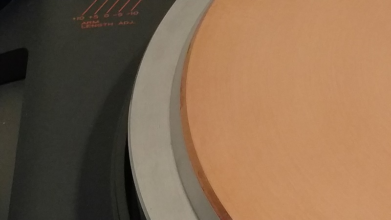
Author's 2022 update: I am now using a 2.5mm thick copper platter sheet above the OEM stainless steel platter sheet. The outer diameter of the bottom side of the copper platter sheet is the same diameter as the outer diameter of the top side of the OEM stainless steel platter sheet. The rim of the copper platter sheet is beveled similar to the rim bevel of the OEM stainless steel platter sheet. With those dimensions, the outer edge bevel of the OEM stainless steel platter sheet continues into the outer bevel of the copper platter sheet. The copper platter sheet has a record label depression on the top side.
Solutions
So then, is the L-07D "doomed forever" to narrow sound staging and limited tonality? Is this the price we must pay and accept for "Metronomic precision that faithfully captures the starts and stops of notes and thus every instrument in the mix " that is absent in belt drive turntables? The answer is a big no! With proper EMI and RFI shielding, the negative interaction of the motor and phono cartridge/tonearm wiring with each other via RFI and EMI can be eliminated with materials that were not available at the time of the L-07D's design. With the proper do-it-yourself (DIY) shielding applied, the improvement in sound stage, tonal spectrum and treble response are so improved that I am at a loss to find the proper quantitative superlative. Once you apply these simple tweaks, you can transform your L-07D into a deck that runs with metronomic precision and puts out a vast sound stage.
Author's 2022 update: I am no longer using ERS paper or Mu metal on my L-07D. I am now using a 2..5mm thick copper platter sheet on top of the OEM stainless steel platter sheet. Please see above.
EMI Shielding
Shielding the motor's EMI fields from the phono cartridge and tonearm wiring (and the phono cartridge's EMI fields from the motor) is as simple as putting an efficient physical EMI barrier between the two. The material of choice for this task is Mu metal. (Pronounced "mew" metal). This material is a sheet metal product that is approximately 80% nickel, 4% molybdenum, and the remainder iron. It is available commercially in 0.004 and 0.006 inch thicknesses. I am using the 0.006 inch thick variety. A single thickness completely eliminates the "wum-wum-wum" during braking, and resolves the sound stage and tonality problems described above. Simply cut out a circular sheet of this material the same diameter as the platter sheet, drill a center-hole, and place it between the subplatter and the platter sheet. EMI interference is resolved at a cost of approximately $25 USD.
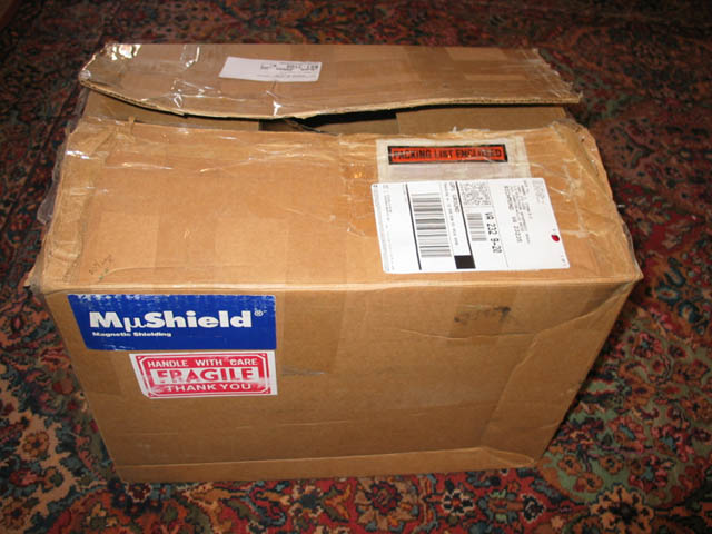
Does the box above contain the solution to the L-07D's sound staging woes?
Yes it does!
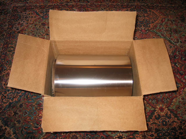
Voila Mu Metal! EMI shielding in sheet metal form.
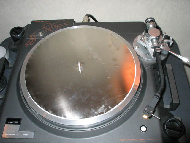
This L-07D's motor and cartridge/tonearm wiring are now shielded from each other's EMI fields and Gaussian effects. (Note the ERS paper disc beneath the Mu metal disc.) After application of the shielding material as shown above, the platter sheet is reapplied, as shown in the photo below:
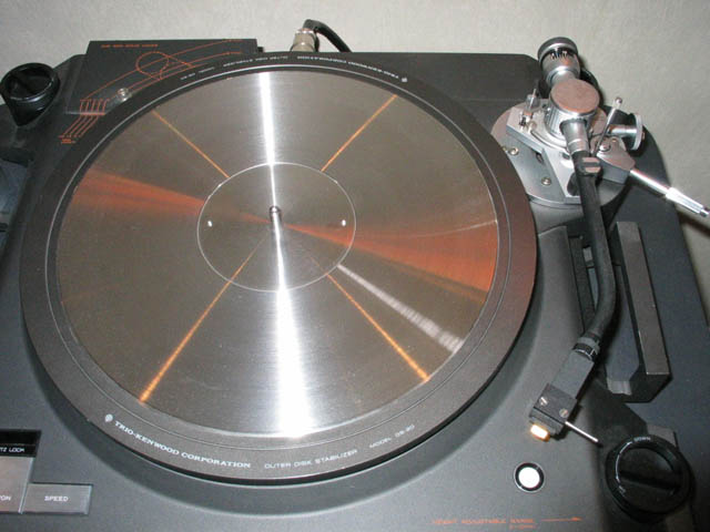
The "finished product" shown above. The shielding is barely visible without the DS-20 outer stabilizer in place (see below), but it is completely invisible with the DS-20 in place.
White paper on Mu metal shielding used on this page.
Author's 2022 update: I am no longer using ERS paper or Mu metal on my L-07D. I am now using a 2..5mm thick copper platter sheet on top of the OEM stainless steel platter sheet. Please see above.
RFI Shielding
Stillpoints makes a paper product called ERS that blocks RFI. It has many audio applications, and can be found on the TweekGeek website at www.tweekgeek.com. The paper comes in 8½ x 11 inch sheets. Thus, it takes two sheets to make a circle of ERS paper the same diameter as the platter sheet. RFI interference is resolved at a cost of approximately $40 USD.
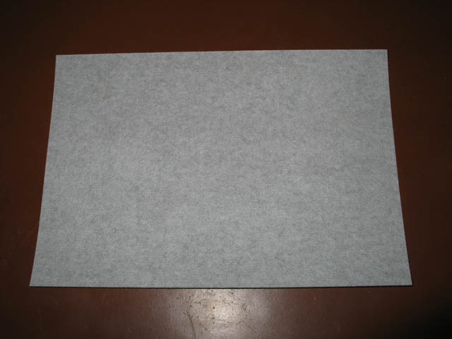
ERS 8½ x 11 inch cloth-paper sheet shown above.
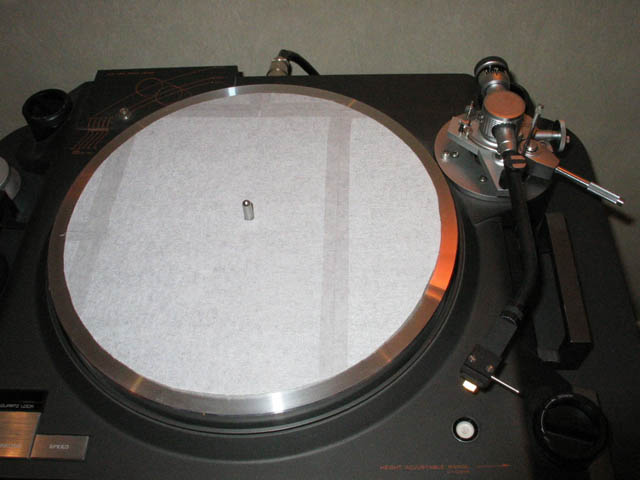
The ERS disc can be made from two pieces of ERS paper. Having made a few of these, I made the above disc from one sheet of ERS paper plus scraps left over from earlier discs made.
Author's 2022 update: I am no longer using ERS paper or Mu metal on my L-07D. I am now using a 2..5mm thick copper platter sheet on top of the OEM stainless steel platter sheet. Please see above.
The Fully EMI and RFI Shielded L-07D
I have been using the following solution: I use a sandwich of materials from bottom-to-top order of: subplatter, ERS disc, Mu metal disc and stainless steel platter sheet. The results are astounding! I believe that this solution will lay to rest prior criticisms of the L-07D's sound staging and tonal palette shortfalls.
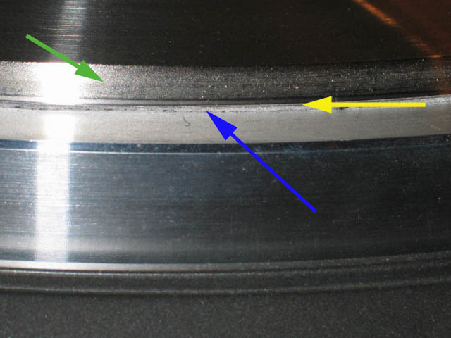
In the photo above, the fully EMI and RFI shielded L-07D platter is shown, with the ERS (blue arrow) and Mu metal (yellow arrow) DIY discs barely visible from side inspection beneath the platter sheet (green arrow). The result is, of course, invisible with the DS-20 outer stabilizer applied. Links to the sources for the materials used for shielding are located on the Links & Contact page of this website.
Some additional thoughts on the subject: I wonder whether the "thumb holes" in the subplatter are EMI shielding defects. I think that it may be worthwhile to obtain a Gauss meter to measure the effects of EMI shielding and interference. It would seem apparent that the methods used above could enhance performance on any direct-drive turntable with similar afflictions. It is my understanding that the Onkyo PX-100M suffers from more pronounced EMI and/or RFI playback effects than does the L-07D.
This subject has been discussed in the L-07D Discussion Group. Several L-07D owners have responded that they do not hear the "'wum, wum, wum'“ through the speakers as the electronic brake is slowing the platter. In my case, my Control Units are all fully rebuilt and upgraded, including the power-supply power-transistors. I wonder if my rebuilt units send more current to the motor during electronic braking than a Control Unit with 25-year-old all-original components.
Interestingly, a multiple Technics SP-10 owner has commented in the L-07D Discussion Group that his SP-10 demonstrates the same "wum, wum, wum" as the L-07D during electronic braking. He further confirmed that the "wum, wum, wum" was completely eliminated with a sheet of Mu metal over the platter and under a cork mat covered by a rubber mat on his SP-10. However, he didn't like the sound. He stated that the image was less focused and more grainy. He theorizes that the Mu metal is itself magnetic, and can affect the cartridge. He theorizes that the sound of the L-07D is improved because the stainless steel platter sheet shields the cartridge from any magnetic effects of the Mu metal.
An L-07D II owner that I know theorizes that the separate stator coils of the generation two motor generates less EMI than the star coils of the generation one motor. He does not notice any "wum, wum, wum" during electronic braking on his L-07D II with either moving-magnet or moving-coil phono cartridges. Even so, he has noticed improvements on his deck using the Mu metal disc, with "slightly silkier highs" .
I have sent some Mu metal shielding discs to several L-07D owners. I have received only positive feedback thus far on the effects of the Mu metal disc on playback on the L-07D.
I think some phono cartridges may better shielded than others from EMI, by design. I think the Mu metal mod is worthwhile if the motor is producing sound-degrading magnetic effects on a particular cartridge/table combination.
Author's 2022 update: I am no longer using ERS paper or Mu metal on my L-07D. I am now using a 2..5mm thick copper platter sheet on top of the OEM stainless steel platter sheet. Please see above.
Anti-skate Thread Replacement
If your anti-skate thread breaks, it is easy to repair yourself. An exact replacement for the original thread is 6-0 clear monofilament nylon surgical suture, Ethicon 689G. You can source this from most medical supply companies. The original anti-skate string end-caps are 3mm in diameter. The original anti-skate string length, when all slack is taken out, is 83mm between the end-caps. This results in an end-cap-center to end-cap-center distance of 86mm. Rather than a bunch of knots, use two knots sealed with a drop of "Crazy Glue" to secure the string to each end cap.
Control Unit Adjustments - The Author's Method in 2022
When the service manuals for the L-07D and L-07D II were written around 40 years ago, digital storage oscilloscopes were not yet invented. The digital storage oscilloscope (DSO) was invented in 1985. So nowadays we have DSO's and other instruments available for Control Unit adjustments.
Oscilloscope: Measures in the Voltage vs. Time domain.
Spectrum Analyzer: Measures in the Frequency vs. Voltage domain.
Modulation Domain Analyzer: Measures in the Frequency vs. Time domain.
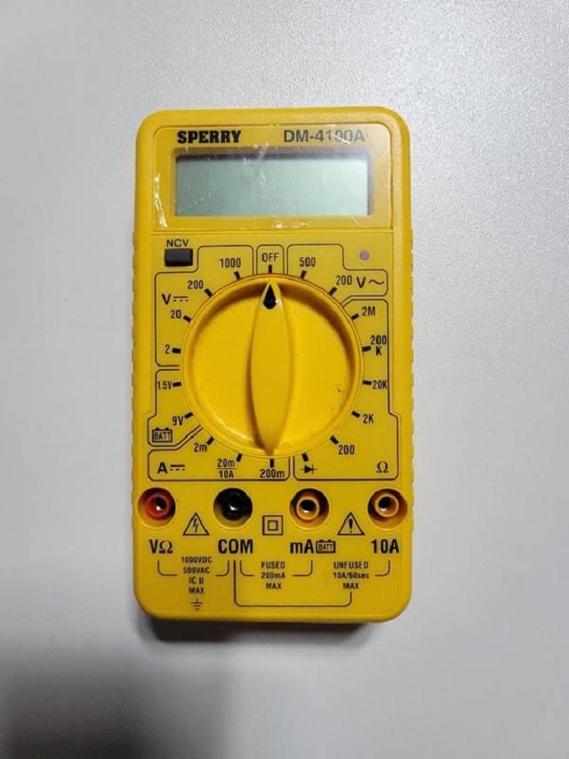
For adjusting Offset during Playback at 33rpm and at 45 rpm, I have found what I feel is a better method for adjusting Offset during Playback than the service manual method. To adjust offset during playback I like a slow acquisition-time multimeter. Slow is good here because the readout changes just fast enough that you can visually see the max + and max - voltages. I use a SPERRY DM-4100A and it works well for this purpose.
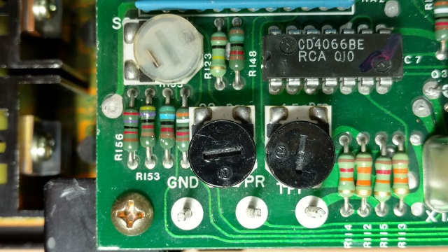
I adjust Offset during Playback with a slow acquisition-time multimeter (I use the one shown directly above). I connect the black/negative wire (with an alligator clip termination on the sampling end) from the DMM to the same ground point that the service manual shows connection to for the ground wire of the oscilloscope probe (GND). I connect the red/positive (with an alligator clip termination on the sampling end) from the DMM to SC-1 on the logic/control board when setting Offset during Playback at 33 rpm. I connect the red/positive (with an alligator clip termination on the sampling end) from the DMM to SC-2 on the logic/control board when setting Offset during Playback at 45 rpm.
I adjust Offset During Playback with the slow acquisition-time multimeter giving readouts during platter operation. The adjustment trim pots for this parameter are BO-1 for 33 rpm and BO-2 for 45 rpm. As an example, I would see continually changing numbers on the readout of the multimeter such as (for example purposes only): +16.1, +11, +5, 0, -5, -11, -15.8, -11, -5, 0, +5, +11, +16.1 etc. repeatedly (offset at playback needs adjustment in this example because +Vmax is +16.1 volts and -Vmax is -15.8 volts). In this example, I would then adjust to get: +16.1, +11, +5, 0, -5, -11, -16.1, -11, -5, 0, +5, +11, +16.1, etc. repeatedly. I am adjusting to get equal +Vmax and -Vmax. Offset during playback trim pots (BO-1 for 33 rpm and BO-2 for 45 rpm) sets the maximum negative voltage of the sine wave driving the motor.
The service manual procedure demonstrates how to set +Vmax and -Vmax for Offset during Playback at 33 rpm and at 45 rpm using an oscilloscope. I have much experience with this method. What makes this method somewhat difficult in practice is that as you watch the sine waves move along the oscilloscope screen, there are some variations in the +Vmax and -Vmax voltages of each individual sine wave. Therefore I prefer an averaging method, such as the one described above.
I generally leave the trim pots for Offset during Startup at 33rpm and at 45rpm alone, unless there is a problem.
For adjusting SC-1 GAIN which is the "wow and flutter adjustment" trim pot, one should first understand what this trim pot does. It varies the gain of the op amp that generates the signal for motor Coil 1 (also known as Coil A). So in effect, adjusting the SC-1 GAIN trim pot varies the gain of, and allows the balancing of, the signal of the Coil 1 (also known as Coil A) and the Coil 2 (also known as Coil B) motor coils against each other - so the coils are not working against each other, resulting speed instability. Motor speed is optimally stable when both motor coils have balanced gain.
The problem with simply using a test record and a wow and flutter meter to measure speed stability of the L-07D is that the accuracy of this method is limited by how perfectly centered the test record spindle hole is and test record flatness. The speed stability of the L-07D is better than the testing limitations of the test record method. With the test record method, what is being measured is the combination of turntable speed stability and test record method physical inaccuracies. Nowadays we have other digital measurement instruments that can measure motor speed stability directly from motor speed feedback from the FG windings. The measurement point in the Control Unit for this is at TPF. By measuring off motor feedback data of motor speed, the inaccuracies of the test record method are eliminated.
The FG windings are on the bottom of the motor, on the other side of the rotor magnet from the motor drive coils. The FG coils do not drive the motor. The spinning magnet rotor generates a square wave in the FG coils which can be sampled at test point TPF in the Control Unit logic/control board.
The FG signal output at 33rpm is a 50 Hz square wave which is measured at TPF. Using a Modulation Domain Analyzer (MDA) such as an HP or Agilent 53310a, which measures frequency vs. time, viewing the MDA readout during playback while sampling from test point TPF on the logic/control board shows the individual contributions of the two individual motor coils (Coil 1 and Coil 2).
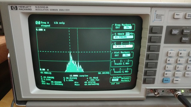
In the MDA photo above, sampling at TPF on the logic/control board at 33 rpm with the SC-1 GAIN trim pot set to minimum gain, we see that the frequency generated by motor Coil 2 (also known as Coil B) dominates.
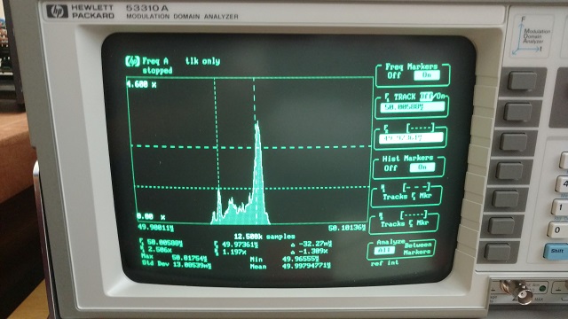
In the MDA photo above, sampling at TPF on the logic/control board at 33 rpm with the SC-1 GAIN trim pot set to maximum gain, we see that the frequency generated by motor Coil 1 (also known as Coil A) dominates.
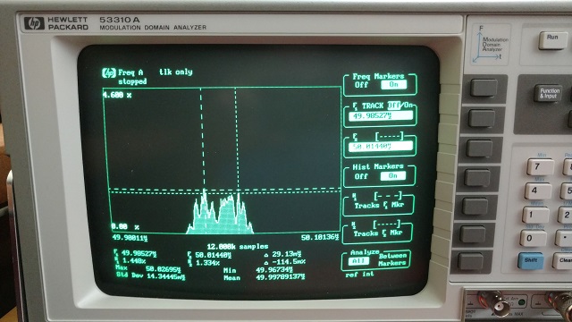
In the MDA photo above, sampling at TPF on the logic/control board at 33 rpm with the SC-1 GAIN trim pot set to final adjustment, we see that the frequency peak generated by motor Coil 2 (also known as Coil B) is equivalent to the the frequency peak generated by motor Coil 1 (also known as Coil A). This equivalency is what I adjust for using this method.
Author's note: A "basic" HP or Agilent 53310a works fine for this purpose. You don't need one with factory options (that generally raise the price of the instrument) such as extra memory, oven crystal oscillator, extra channel, or other options.
Options for adjusting SC-1 GAIN without a MDA include using a wow and flutter meter with a test record (usually done with a 3000Hz or 3150Hz test record tone) measuring the output from one channel of the the preamplifier. Another option is using a wow and flutter meter that can measure a 50Hz signal and measuring at test point TPF on the logic/control board. My Grundig GA 1000 (German-made) "Gleichlaufanalysator" wow and flutter meter can measure signals with a frequency as low as 1 Hz.
Test records can have inaccuracies in tone frequency and how perfectly centered the spindle hole is. Such inaccuracies can affect wow and flutter measurements when using a test record with a wow and flutter meter. The DIN 545 test record is considered to be one of the more accurate test records. The DIN 545 is a 33 rpm test record consisting of multiple tracks of 3150 Hz test tones on both sides of the record from outer groove to inner groove.. All tracks on the DIN 545 test record are 3150Hz tracks.
When adjusting SC-1 GAIN based upon measurements of FG output at test point TPF on the logic/control board, you can decide if you want to take measurements without a record on the platter and therefore measurements will be with no stylus drag, or with a test record playing to add constant stylus drag.
**Always, always, always, each and every time without fail - always make sure the turntable is turned off and the mains disconnected before attaching or detaching any test probe or wire used for sampling from any test point in the Control Unit!! Test probes and test wires can easily short out circuitry and cause major damage!! Use immense care to prevent shorting circuitry when doing any electronic adjustments to the L-07D!!
This method is only a guide line. The author is not responsible for any damage that may be done to any part of the turntable, persons or anything else resulting from any servicing.
DIY Tonearm Rewiring
The following was discussed and posted on the L-07D Discussion Group in September 2019, and is reproduced here with permission from the author:
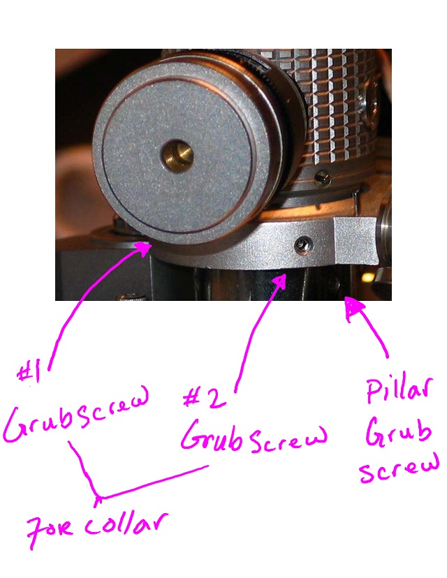
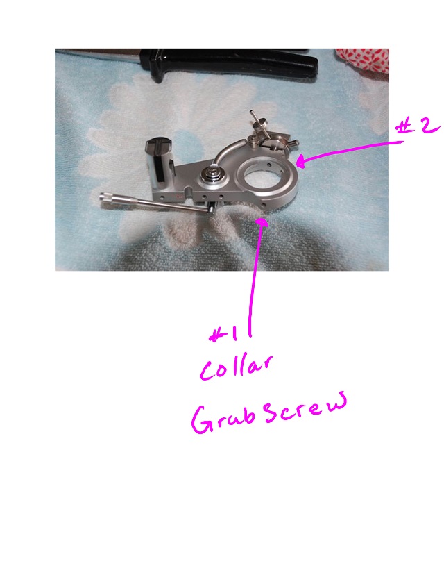
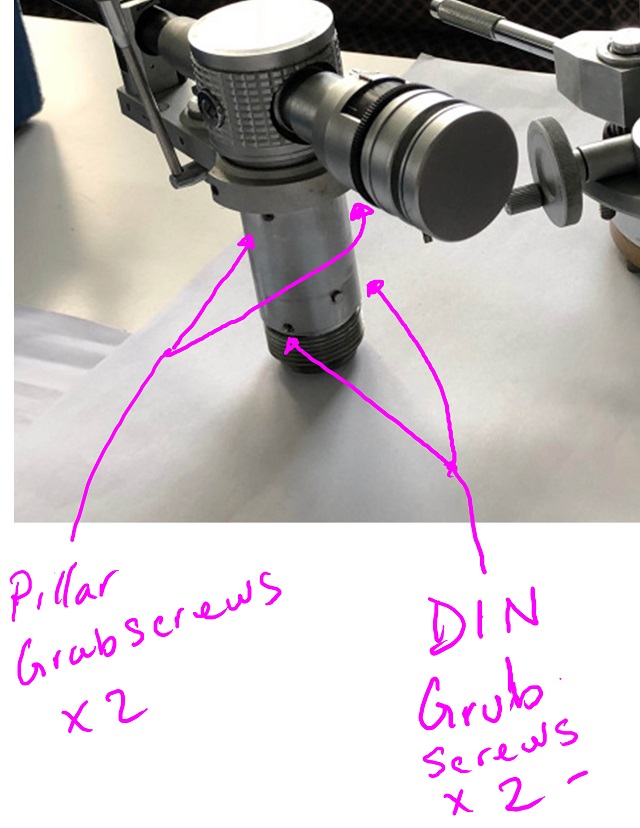
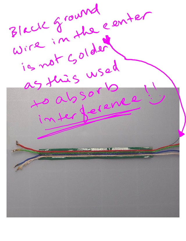
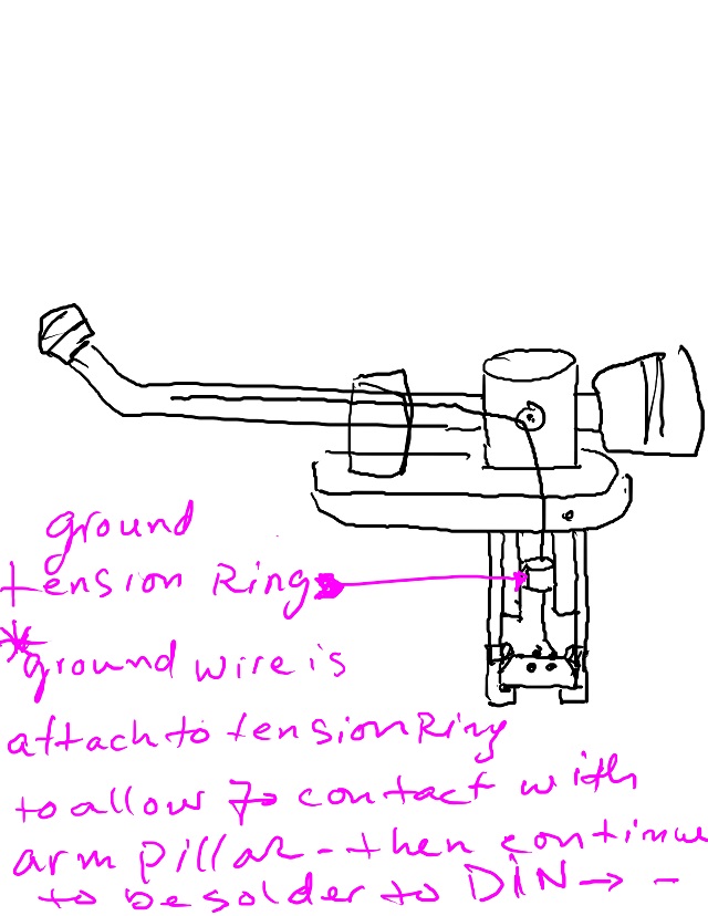
Cardas is good for Rega and such tonearms.... but for the L-07 you would definitely want something really good. Re-wiring this tonearm is like re-wiring any Rega tonearm, the only difference is that you have to unlock the two collar grub screws. The rest is just the 4 Pillar and DIN screws on the arm Pillar. 2 for the Pillar and 2 for the DIN. Once you get the DIN out just unsolder the wires and pull it out through the Headshell collar. **** remember to a attach a nylon fishing string with the wires before pulling the wires out, this will allow you to fish back the new wires that will replace the old ones**** Then reverse the procedure. ***There is a ground wire that is floating inside the armwand and is connected inside the arm pillar.
Rewiring the L-07 tonearm is fairly easy and straight forward... More important is that this is the best time to upgrade the internal wires to something really good as well... maybe Kondo or Deskadel tonearm wires.
Almost all high quality silver internal tonearm wires are more flexible than Cardas.... for this reason I recommend Kondo, Deskadel and or Van Den Hul (VDH MCS-150M) wires. However if you're looking for a wires that is the similar or the same as the original then you have to find silk wrap litz wires, they are very flexible and musical. Cardas Clear and the Regular Cardas are only 33 and 34 AWG with 7 strands per conductor. Rupalit from Pack Litz Wire on the other hand are much thinner, more flexible and contain 20 to 40 strands per conductor depending on your preference. Just go to the site and click on the data specs. 35 strands 48AWG or 30 strands 46AWG should be very good or go thinner if you want.
Here’s the url for the Litz wires: https://www.packlitzwire.com/products/litz-wires/rupalit-classic-plus/ Just click on the data specs to view the what you need... 30-35 strands 46-48AWG should be good.... go thinner if you want. These wires are individually coated per strand... so you have to thin them before you can solder.
This method is only a guide line. The author is not responsible for any damage that may be done to any part of the turntable, persons or anything else resulting from any servicing.
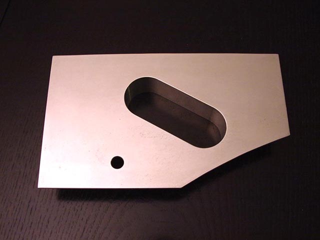
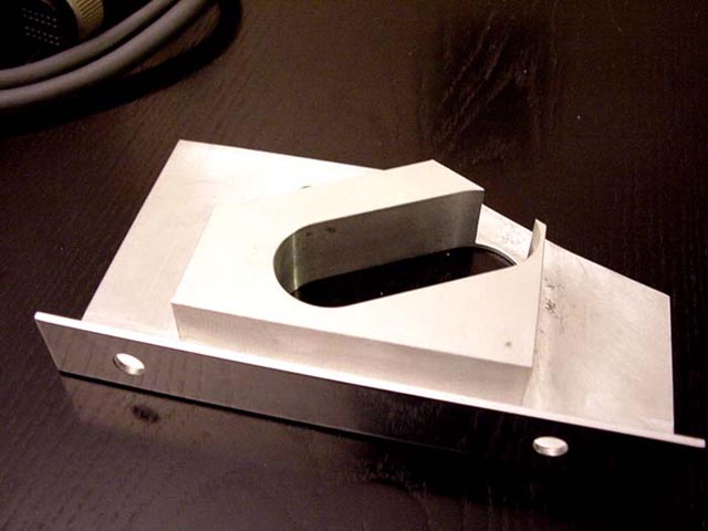
DIY Sub Arm Base
Custom made Sub Arm Bases are available from Vantage Audio in the U.K. Shown below are Do-It-Yourself (DIY) Sub Arm Bases which were made by L-07D owners:
IEC Socket
This is one modification that I am opposed to for several reasons. Firstly, replacing the factory AC socket with an IEC socket eliminates the dual voltage capability of the L-07D. I suppose that if an IEC socket were added with a separate voltage selector switch, that would preserve the dual voltage capability. Secondly, upgraded power cords are available to work with the original socket. Thirdly, the L-07D should not be grounded through the power cord to house ground. The Control Unit should only be grounded to the phono stage, via the rear ground point on the Control Unit. I have seen quartz lock problems from ground loops when the chassis of the Control Unit is grounded to house ground. If you use an IEC connector, I recommend that you do not connect the center connector to anything inside the Control Unit. Finally, I am a purist and I also think the original equipment AC cord is fine for this application.
Record Cleaning
Author's Current Method
My current method for cleaning records:
Step 1. First I clean in the sink with a Groovmaster label protector using a Disc Doctor brush as follows:
Step 2. Groovmaster label protector kept on and into the Ultrasonic Bath, utilizing a Bransonic 3510 Ulrasonic bath cleaner. Bath solution is 8oz of 98% isopropyl alcohol in 1 and 1/2 gallons of DW. Cycle for 5 minutes to a third of the record, or 15 minutes total. The US machine that I use can handle two records at a time with Groovmasters.
After years of experimenting with record cleaning, I have reached the following conclusions:
RCM cleaning alone may not adequately clean a very dirty and/or dusty record. If you doubt this, use a velvet record brush on a RCM cleaned record. The dirtier the record was to start with, the more you will pull up with the brush.
Records can be maximally cleaned without expensive commercial RCM fluids, IMO.
This method is only a guide line. The author is not responsible for any damage that may be done to any record, persons or anything else resulting from using the above record cleaning method.
All trademarks and rights belong to the OEM and are reproduced here for information purposes only. Copyright © 2003-2022. All rights reserved.