![]()
![]()
![]()
![]()
![]()
![]()
![]()
![]()
![]()
![]()
![]()
![]()
![]()
![]()
![]()
![]()
![]()
![]()
![]()
![]()
![]()
![]()
![]()
![]()
![]()
![]()
![]()
![]()
![]()
![]()
The Motor and Electronic Engineering
The motor is the heart of the deck's performance and amazing -94db rumble figure. A constant-current DC Servo motor was chosen for its ability to maintain a constant torque, and provide speed feedback info to the controller which regulates platter speed via a Phase Lock Loop (PLL). A coreless slotless motor was chosen to eliminate torque ripple. A brushless motor was chosen to eliminate brush wear and rumble. The main bearing is integral to the motor. A Teflon thrust bushing runs inside a true oil bath bearing well. The bearing shaft is 12 mm thick and made from hardened steel, as is the captured ball bearing. The bearing sleeve is bronze. A layer of oil between all moving parts assures long life and smooth operation of the bearing. The die-cast motor housing contains aircraft style rigid reinforcements within the motor casing. The motor contains not only the required rotor and stator for rotational movement, but also a magnet levitation function that puts an upward force on the spinning platter to unload the bearing and reduce rumble.
The main criticism of less well designed PLL systems is that they don't react fast enough to correct speed variations and the corrections overshoot the mark. The result is audible wow and flutter. The L-07D completely avoids this pitfall by yet another innovative design. The massive platter and motor torque establish an extremely high moment of inertia to fight stylus drag and prevent transient load variations from affecting platter speed. The PLL system plays backup, only being activated when platter speed varies by +/- 3.7% at 33.33 rpm or +/- 5.0% at 45 rpm. Within that range, PLL is maintained and the motor makes no speed corrections. Motor speed is regulated by a quartz crystal (vibrating at 5.5296 MHz) to precisely 33.33 or 45 rpm with zero tolerance.
Two brakes are provided, one electronic the other mechanical. As soon as the Operation Button is pressed when the platter is on, the electronic brake will slow the platter very quickly and smoothly. Once the platter slows to one fifth of operational speed, the solenoid operated mechanical brake is applied. The mechanical brake deploys a felt brake shoe which engages the platter to bring it to a complete stop. The entire operation of stopping the platter takes only two seconds. The mechanical brake is released when the Operation Button is pressed again to start play. There are only two buttons on the top of the deck. The Operation Button for start/stop and the Speed Button to select 33.33 or 45 rpm.
In describing the motor, the following is stated in the L-07D instruction manual and brochure:
Dynamic compensated motor
The most important point in improving the phono-motor is to remove cogging and torque ripple. Theoretically, it is possible to build a motor without torque ripple, but in practice such a motor is impossible because of machining accuracy and viscous resistance. The motor coil was formerly driven at constant voltage. In the L-07D, however, the motor coil is driven at constant current. Therefore, counter-electromotive force in the coil can be ignored and control can be more precise.
The L-07D uses double servo coupling, which automatically switches the control method when the speed differs by +/-3% from the rated speed. When the speed difference is beyond +/-3%, the speed is controlled to obtain a large torque and, when it is less than +/-3%, the phase is controlled to obtain a wide lock range and large phase gain. Further, at a speed of +/-3%, the circuit coupling is changed from DC to AC to reduce influences from the motor drive circuit and the motor offset.
If the moment of inertia varies to a great extent (e.g. if Kenwood's disc stabilizer DS-20/DS-21 are used), the dynamic parameter (time constant) can be changed.
The motor itself is a improved design, using a new hard aluminum die-cast casing and an exceptionally rigid, 12mm diameter stainless steel center shaft around which the entire direct-drive system revolves. In this way, the motor has a fixed thrust to ensure high mechanical impedance under all dynamic conditions.
External Dynamic Phase Compensator controls ambient changes
The direct drive system of the L-07D incorporates a highly sophisticated quartz-lock, speed-phase double servo control and constant-current type motor to maintain high accuracy in motor speed. But even the best of servo-systems, various ambient conditions during turntable operation can produce speed fluctuations that can ultimately affect perceived sound quality. Such factors include temperature and humidity, and changes in viscosity resistance due to heat generated by the oil in the bearing system. Kenwood engineers therefore incorporated an external logic control circuit that automatically compensates for ambient changes to within +/- 3 % of rated speed. When a record stabilizer is used, changing the parameters, the phase compensator can be switched to a different value.
This turntable is driven by a DC motor, and will work equally well on 50 Hz or 60 Hz power frequencies.
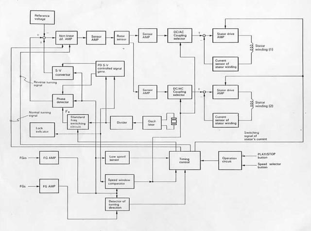
The Logic Diagram above displays the electronic operation of the deck.
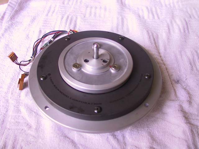
The picture above is the top of the L-07D motor. The two holes in the aluminum rim of the motor are two of four that are used to center the motor in the plinth.
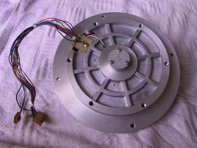
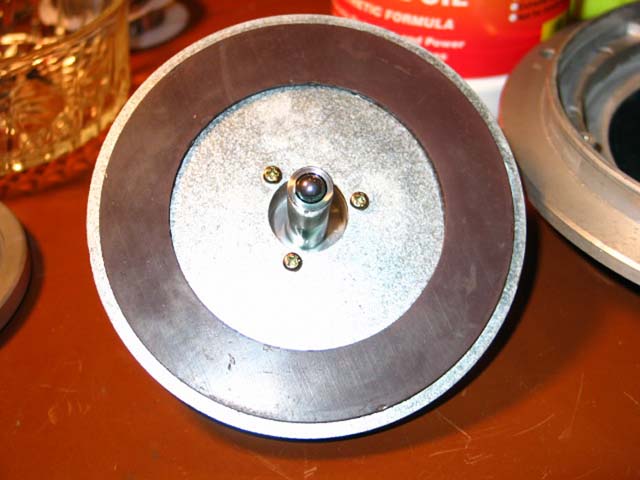
The picture above shows the bottom of the L-07D motor. Note the rigid casing design which supports the centered bearing tube within the motor. The six holes around the bottom of the casing are for bolting the motor to the plinth with large hex-key round-head bolts. The photos below were taken during a motor servicing to inspect the motor and lubricate the bearing:
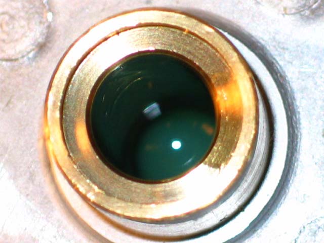
Bearing tube filled with new oil shown above.
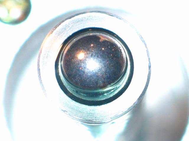
The picture above demonstrates the massive bearing shaft with the captured ball bearing. The ball bearing mates against the Teflon thrust plate in the bottom of the bearing well. Thus, the platter spins on a shaft with a ball bearing on the bottom of the shaft. The ball bearing runs on a thick Teflon thrust bushing covered with oil. The result is long life, freedom from friction, no side to side play due to extremely tight tolerances and excellent rigidity.
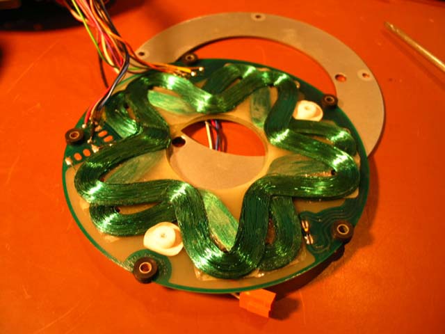
The picture above shows the stator. The two overlapping A and B coils form a continuous loop above the magnetic rotor. Thus the motor is coreless, slotless and brushless. There is no physical contact between the rotor and the stator.
Magnetic pad on the underside of the rotor induces the FG windings in the PCB in the bottom of the motor housing during motor operation to produce an FG signal that is fed into the control IC to control motor speed. The FG signal is also used to detect reverse movement.
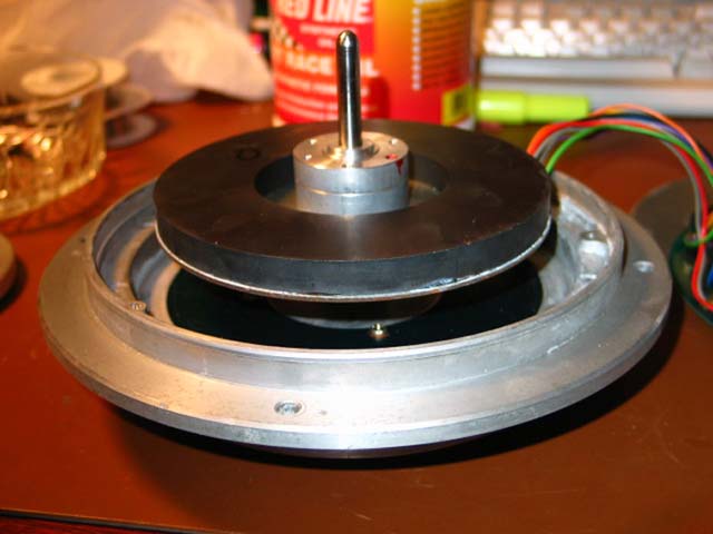
The magnetic rotor is seen sitting high up in the bearing housing in the picture above. Air gets trapped in the bearing tube when the parts are put back together. It takes a while for gravity to expel the air and for the bearing to seat due to the tight tolerances of the bearing assembly. The PCB in the bottom of the motor housing contains the FG windings which produce a signal when the motor is turning as a result of the rotating magnet in proximity above it. FG signal frequency at 33.33 rpm is a 50Hz square wave. The FG signal is fed into the control IC to control motor speed. The FG signal is also used to detect reverse movement. Once the assembly seats, the stator PCB is installed face down, so that the stator coils are about 2mm above the top of the magnetic rotor, allowing clearance between the key parts. Thin brass shims are used to set this clearance. Then the top cover goes back on with five screws. Finally the platter mounting plate is secured to the rotor shaft, and reassembly is complete. (See top view of motor above.)
All trademarks and rights belong to the OEM and are reproduced here for information purposes only. Copyright © 2003-2022. All rights reserved.