![]()
![]()
![]()
![]()
![]()
![]()
![]()
![]()
![]()
![]()
![]()
![]()
![]()
![]()
![]()
![]()
![]()
![]()
![]()
![]()
![]()
![]()
![]()
![]()
![]()
![]()
![]()
![]()
![]()
![]()
Evolution
The L-07D has gone through a series of evolutionary changes during the deck's production run. They range from minor variations to a second generation of the deck, the L-07D II.
Control Unit Cover
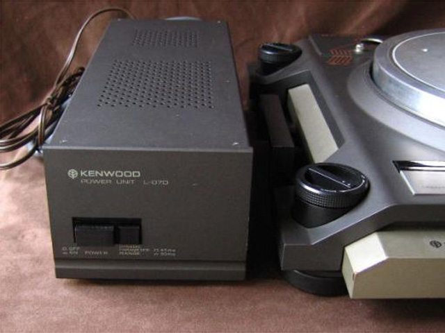
The earliest production Control Units have two separate sections of cooling vent holes in the top cover and are labeled as "Power Unit", as seen in the following picture:
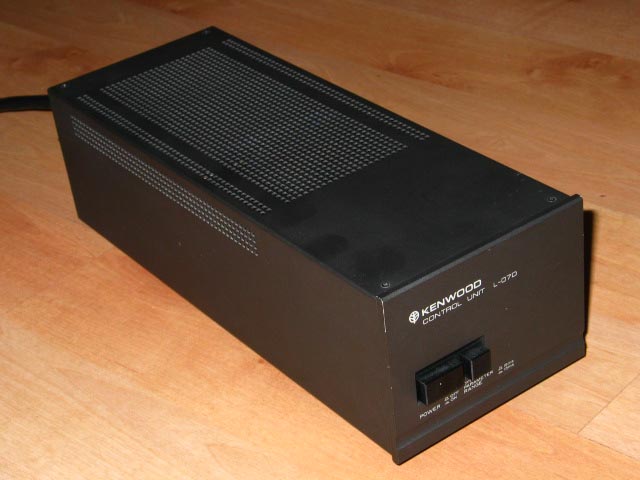
Most Control Units produced were labeled as "Control Unit" and came with the type of top cover shown below:
Motor Cover
The motor top cover came in two versions. The earlier version had dark gray paint and white lettering. The later version had light gray paint and black lettering:
Earlier motor cover plate shown above.
Later motor top cover shown above.
Headshell Finger
The headshell finger came in two versions. The earlier version had a nail-head end and a solid finger bar. The later version had a smooth end and a cutout in the finger bar:
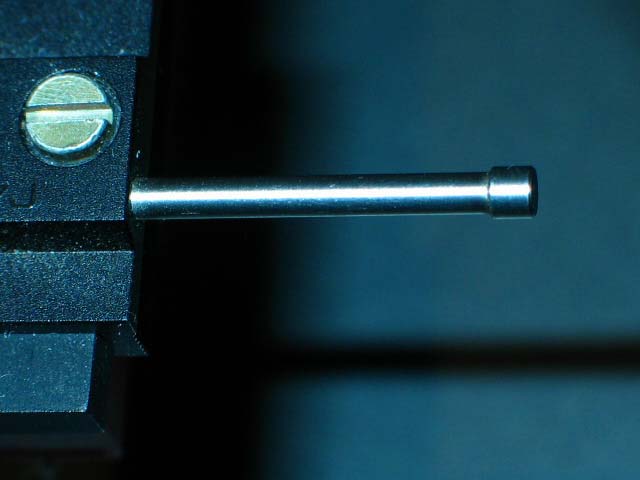
Earlier style headshell finger shown above.
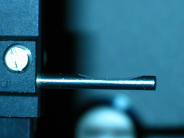
Later style headshell finger shown above.
Bias String Caps
The bias string caps came in two versions. The earlier version had chrome-plated metal end caps. The later version had black plastic end caps:
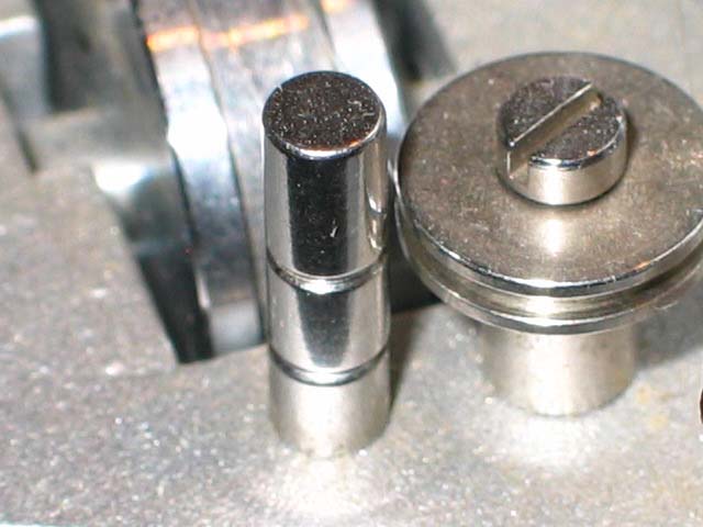
Earlier style chrome-plated metal bias string end cap shown above
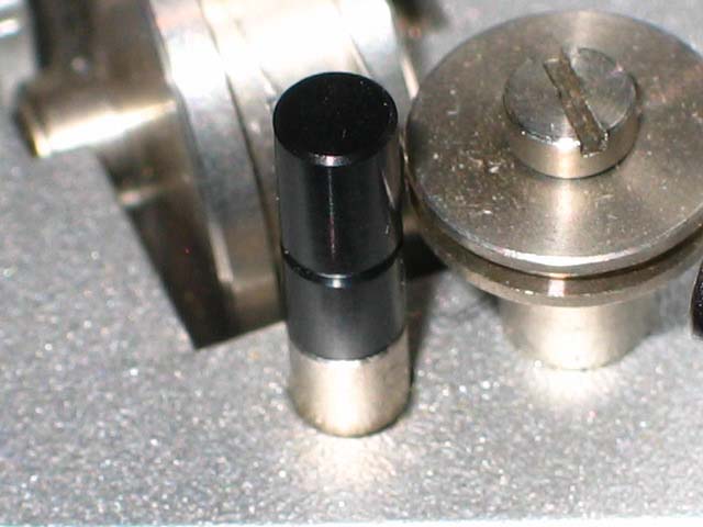
Later style black plastic bias string end cap shown above.
Anti-skate Mechanism
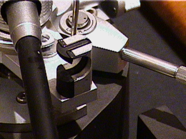
A very early or a prototype version of the tonearm had some anti-skate mechanism differences from usual production tonearms. The fixed portion of the tonearm had a stalk instead of a bias string end cap for attachment of the bias string to the fixed portion of the tonearm. The stalk has a groove for the bias string, as does a bias string end cap. The pulley for the bias string has sharp edges and does not rotate.
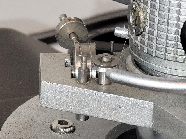
Very early or a prototype version of the tonearm shown above. For this tonearm, a reproduction bias string end cap on one end of the bias string and a simple loop on the other to go around the groove in the stalk made this anti-skate mechanism functional.
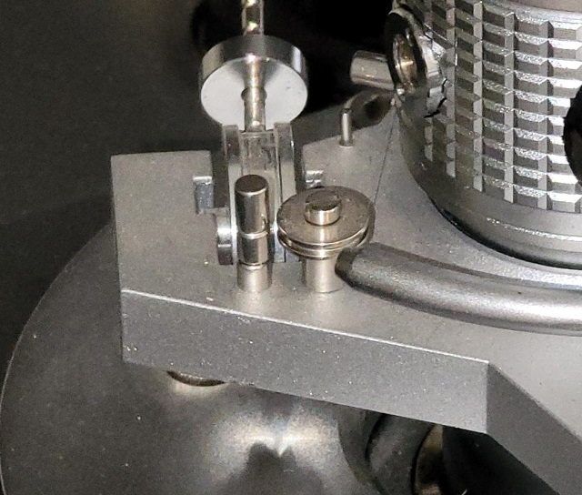
Usual production tonearm shown above for comparison.
Circuit Boards
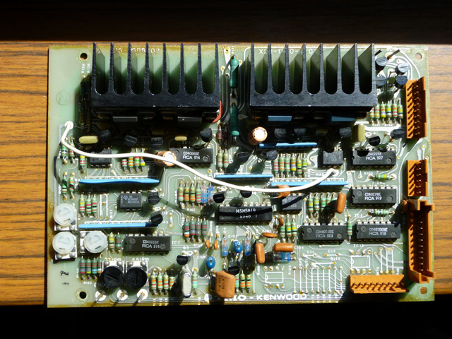
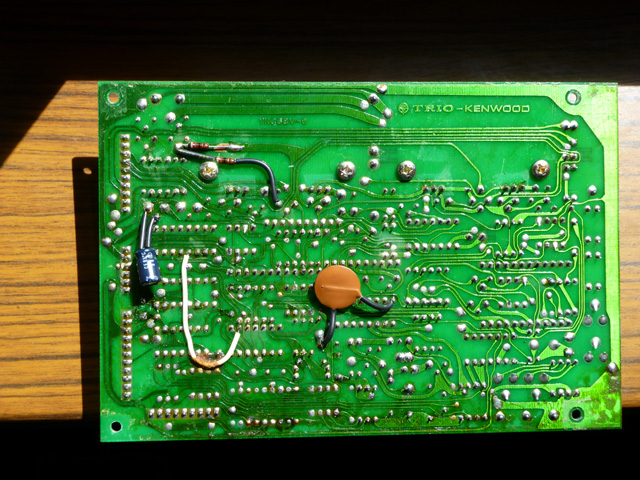
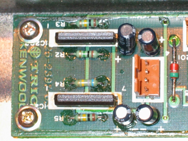
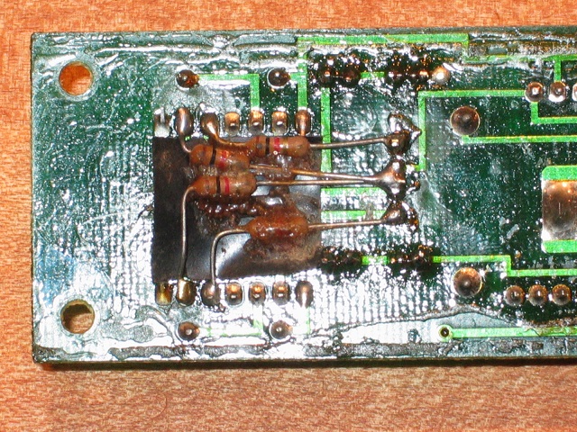
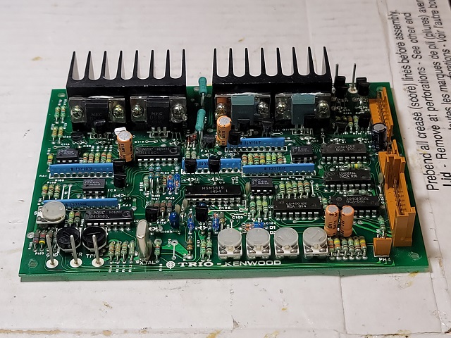
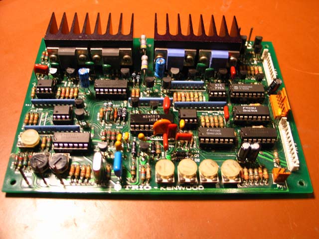
The switching PCB (Printed Circuit Board) came in two versions. The earlier version had four fewer capacitors on the board than the newer version. The earlier version was cut for the four additional capacitors (C301, C302, C305, C306), but the capacitor mounting points on the underside were filled in with solder!
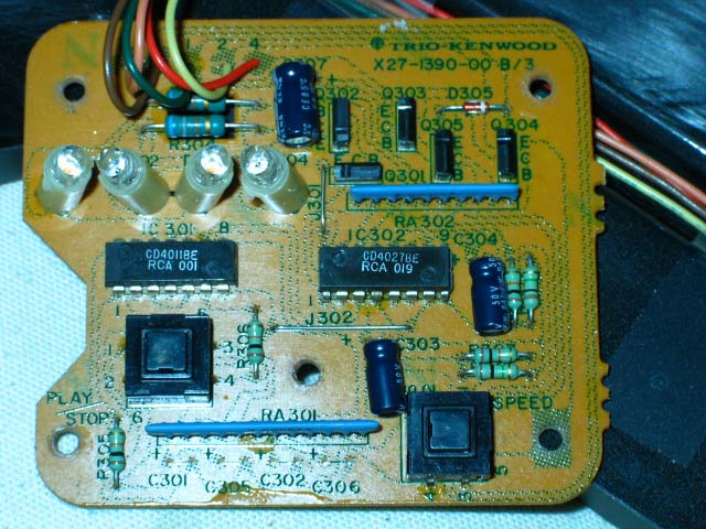
Earlier Version of Switching PCB shown above. Note cutouts for capacitors on the bottom.
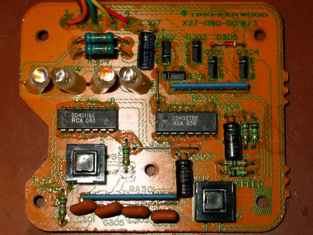
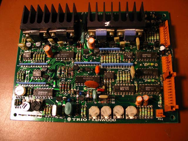
Later version switching PCB with the four additional caps installed. This PCB contains the wiring traces to these caps on the underside.
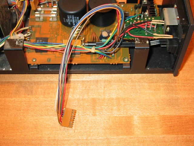
The earliest version logic PCB had no trim pots to adjust Offset during playback. This early PCB had less board components and had a nine-pin PH4 connector where the two-pin connector is usually located. Pics of this earliest version logic PCB, Control Unit and connector PCB are shown in the following photos:
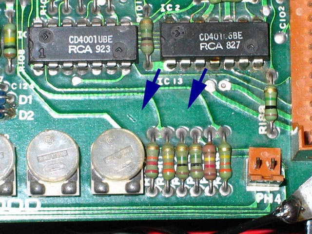
Earlier versions of the logic PCB in the external Control Unit had no components soldered to the underside. Later versions have two resistors soldered to the underside, and a wire jumper. The two resistors are R192 and R193 which appear in the L-07D II service manual schematic, but they are not in the L-07D service manual schematic. In practice, these resistors allow a greater range of Phase Lock Loop adjustability at trim pots VR33 and VR45. To convert an early generation board to a later generation board, the following steps are/were taken:
1. Interrupt original top trace between (Right/IC8 side of) C115 and Pin 1 of IC 10.
2. Solder in 47K resistor on underside of board from (IC8 side of) C115 to Pin 1 of IC 10.
3. Interrupt trace on underside between solder point under R120 to solder point under the number “6” of Q6.
4. Solder in 47K resistor between solder point under R120 and solder point under the number “6” of Q6.
5. Solder in Jumper on underside of board from Pin 10 of IC 8 to (Left/IC8 side of) C117.
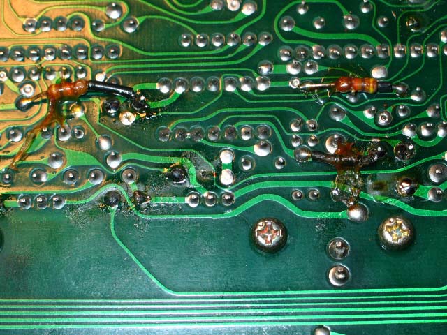
Factory installed R192 and R193 resistors on later model Logic PCB underside shown in the photo above.
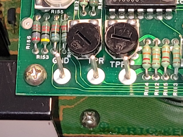
The logic board has five test points: GND (Ground), TRP, TPF, SC1 and SC2. On some logic boards the test points are long posts. On other logic boards the test points are short with a small hole and appear to be made from brass. These variations are shown in photos below.
Long GND, TPR and TPF test points are shown in the photo above.
Long SC1 and SC2 test points are shown in the photo above.
Logic PCB with long test points shown above.
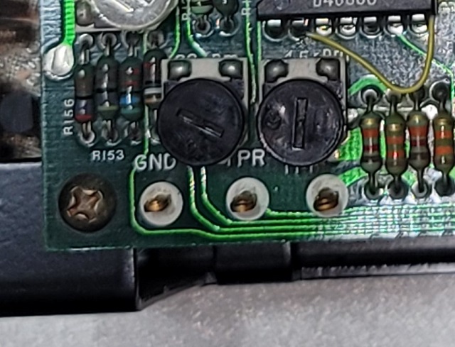
Short GND, TPR and TPF test points are shown in the photo above.
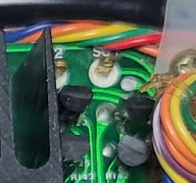
Short SC1 and SC2 test points are shown in the photo above.
Logic PCB with short test points shown above.
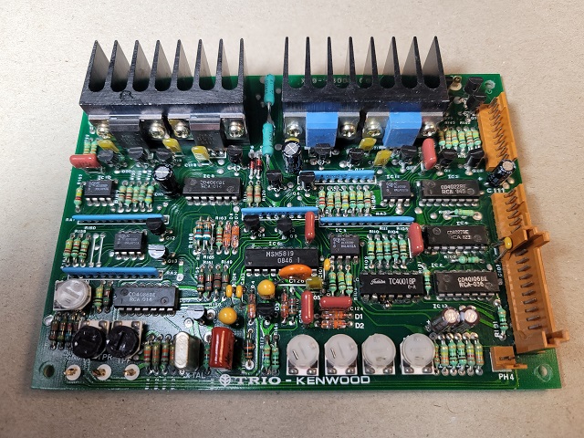
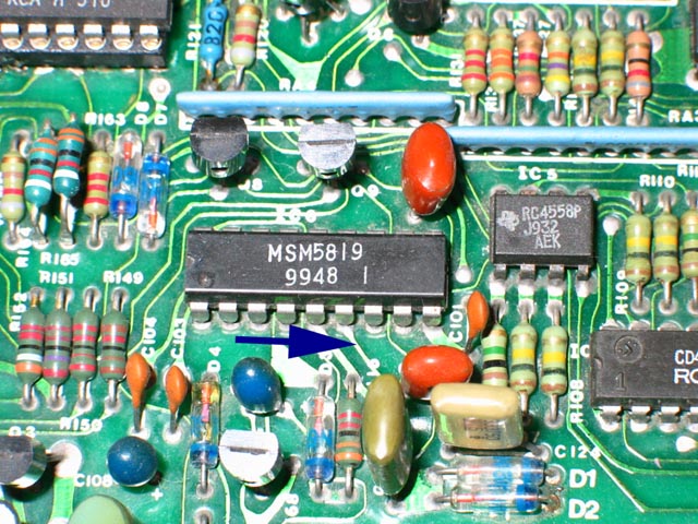
A variation in circuitry is seen in sets that only have three electrolytic capacitors on the Logic PCB, instead of the five electrolytic capacitors seen on most Logic PCB's. On this variation, C127 and C128 have been placed on the X27-1390-00 C/3 PCB which is the PCB connected to the Dynamic Parameter Switch. (The X27-1390-00 C/3 PCB is the smallest of the three PCB's in the Control Unit). Also on this variation, C111 and C126 have been relocated to the underside of the Logic PCB. See the following pictures:
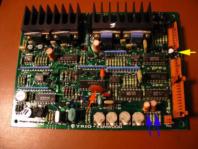
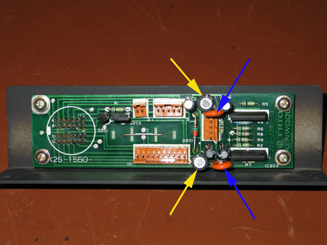
In the photo above the usual version of the Logic PCB is seen with five electrolytic capacitors on the topside of the PCB. C111 is referenced by the yellow arrow. C126 (ceramic capacitor) is referenced by the orange arrow. C127 and C128 are referenced by the blue arrows.
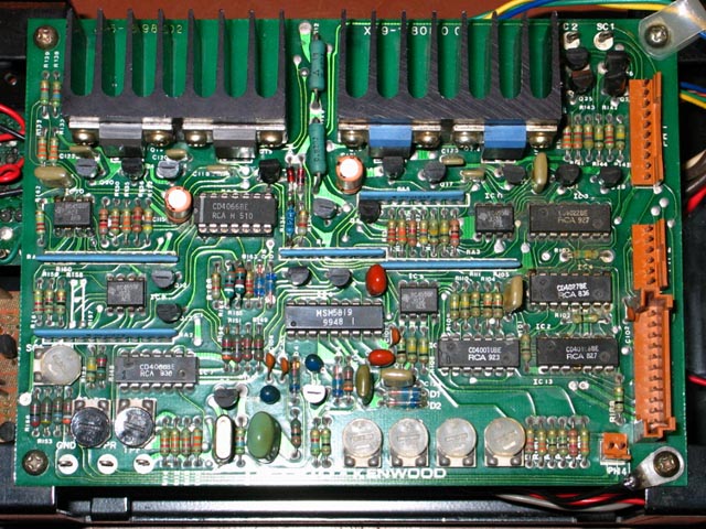
As the photo above shows; C111, C126, C127 and C128 are not present of the top surface of the logic PCB on this variation.
In this variation C111 has been relocated from the position referenced by the arrow above on the top side of the Logic PCB to the underside of the Logic PCB as shown by the photo below:
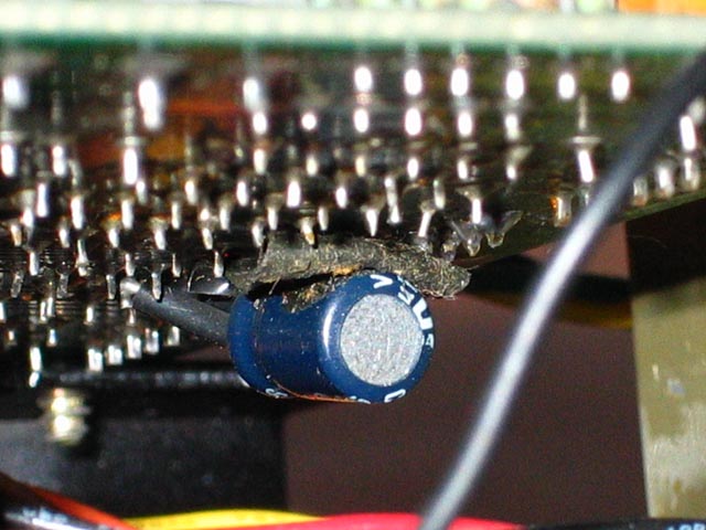
In this variation C126 has been relocated from the position referenced by the arrow above on the top side of the Logic PCB to the underside of the Logic PCB as shown by the photo below:
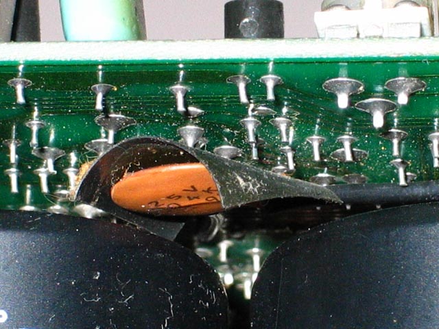
In this variation C127 and C128 have both been relocated from the positions referenced by the arrows above on the top side of the Logic PCB to the underside of the X27-1390-00 C/3 PCB as shown by the photo below:
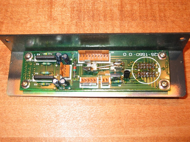
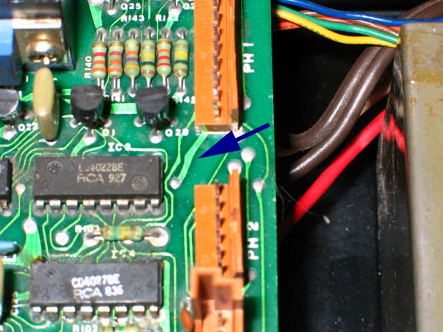
It should also be noted that on this variation where there are only three electrolytic capacitors on the Logic PCB, the rear turntable connector PCB does not have the L1 and L2 inductors that are present on sets with the five electrolytic capacitor Logic PCB as shown in the photo below.
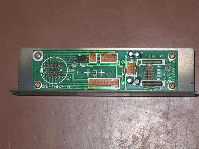
The photo above shows the most common variation of the rear connector PCB (X25-1550-00). This PCB contains the L1 and L2 inductors (yellow arrows, upgraded components shown) and the C5 and C6 0.1 uF ceramic capacitors (Blue arrows, upgraded components shown) in dedicated, labeled slots on the PCB.
In the rear connector PCB variation shown above, there are no L1 or L2 inductors and there are no C5 and C6 capacitors on this PCB. (See information on corresponding logic PCB variation above.)
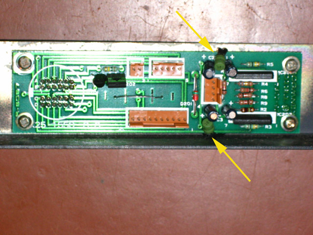
On yet another variation of the rear connector PCB as shown above, the L1 and L2 inductors (yellow arrows, original inductors) are present, but they are hard-wired to the underside of the PCB.
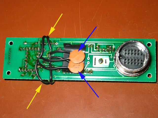
The photo above shows the underside of the rear connector PCB where the L1 and L2 (yellow arrows) inductors are hard-wired to the underside of the PCB. The C5 and C6 capacitors (blue arrows) are also present on this variation, and they are also hard-wired to the underside of the PCB.
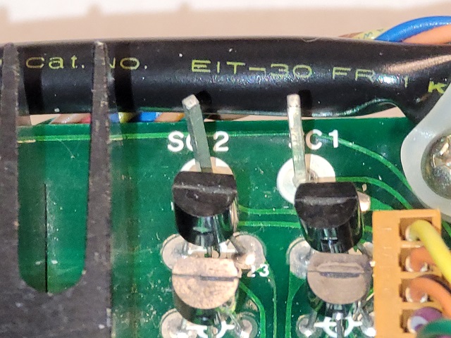
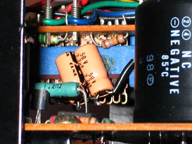
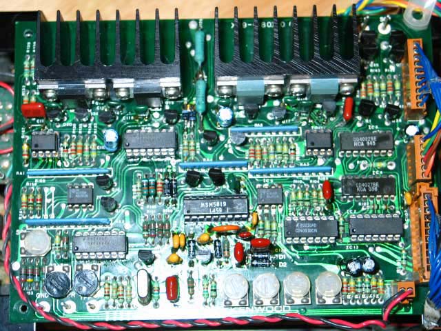
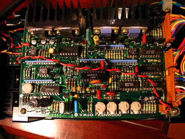
![]()
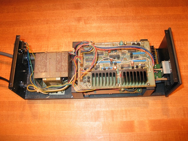
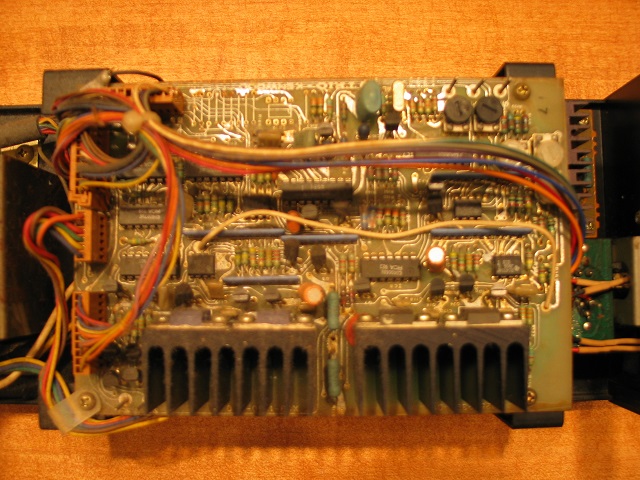
I have seen two control units with the above power and signal transistors that were original as manufactured.
The L-07D II
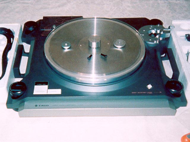
The above evolutionary changes led to the final evolution, a second generation (Mark II) deck. The L-07D II contained all of the evolutionary changes that occurred during production of the L-07D, and others. Most notably, the L-07D II had footers that contained an adjustable spring suspension. The L-07D footers were solid. The tonearm rest on the L-07D II contained a sliding lock. The tonearm rest on the L-07D captured the tonearm pipe with a rubber grommet. The rear connector on the L-07D II was rectangular and was a press-fit. The L-07D rear connector used a JAE (Japan Aviation Electronics, Industry, Ltd.) chrome metal connector with a screw-on collar. The L-07D II motor's stator PCB used six separate coils which were not evenly spaced around the PCB. The L-07D motor's stator coil used two star coils that were evenly spaced around the PCB.

L-07D II identified most easily by the footers, which are flat on top. The tonearm rest has a locking mechanism operated by a slider bar on top. The standard Plexiglass platter dust cover is shown (atop a protractor disc) on the platter in the photo above.
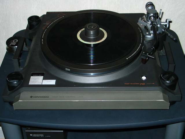
L-07D (shown above) identified most easily by the footers, each of which have a central beam used to turn the adjusting knob. The tonearm rest has a black rubber grommet that captures the tonearm pipe. The photo above also shows the optional DS-20 and DS-21 stabilizers.
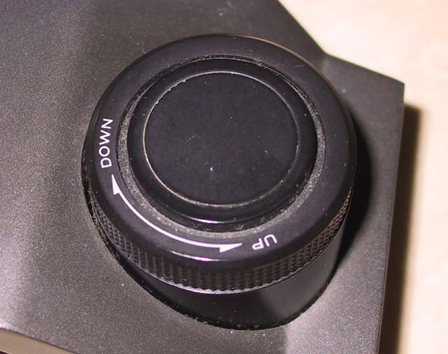
L-07D II footer, top view, shown above
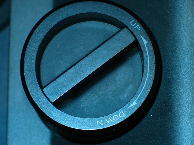
L-07D footer, top view, shown above.
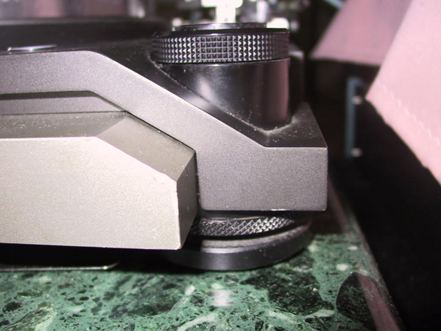
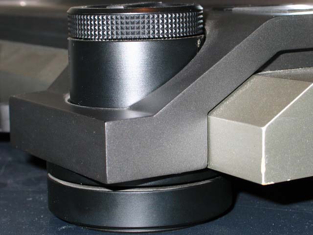
L-07D II footer, side view, shown above. The knurled knob on the bottom of the footer is used to adjust the spring tension of the suspension. Only the L-07D II had a suspension. The L-07D footers are solid.
Side view of L-07D footer shown above.
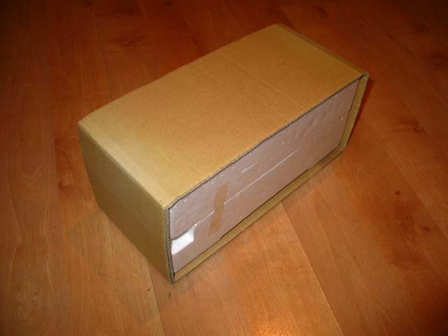
L-07D II tonearm case shown above with tan cardboard outer box
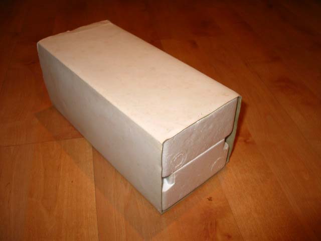
L-07D tonearm case shown above with white cardboard outer box.
L-07D II tonearm with newer style tonearm rest shown above. Sliding bar locks tonearm in rest.
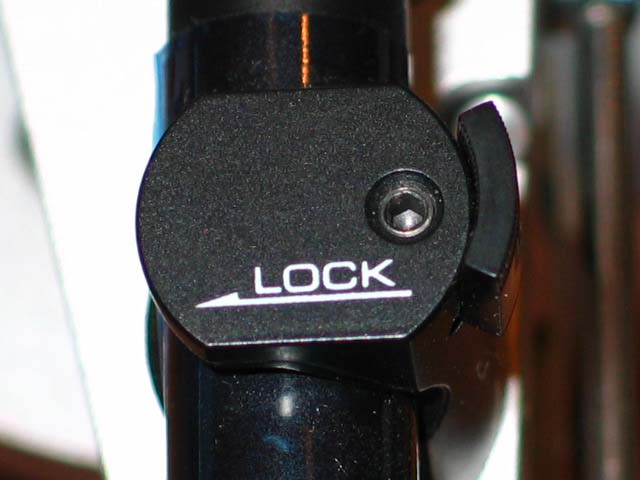
L-07D II tonearm rest with slider moved to the left, locking tonearm pipe to the tonearm rest.
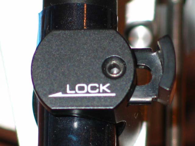
L-07D II tonearm rest with slider moved to the right, unlocking tonearm pipe from the tonearm rest.
L-07D tonearm rest shown above. The rest captures the tonearm via a spring reinforced rubber grommet.
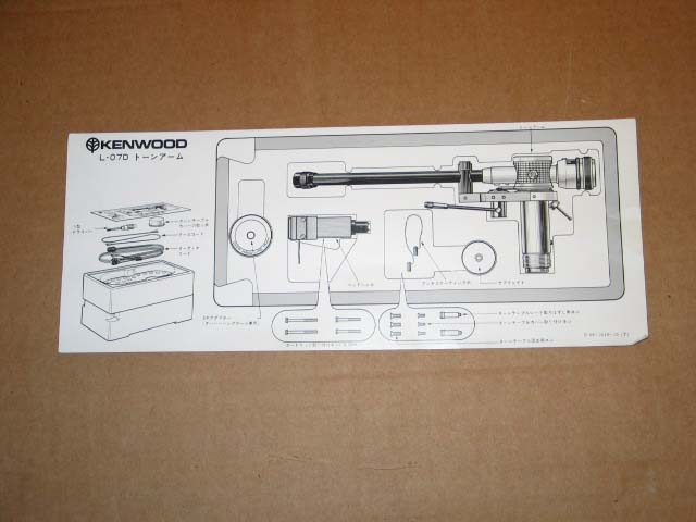
L-07D II tonearm part description card shown above, identified by tonearm rest detail.
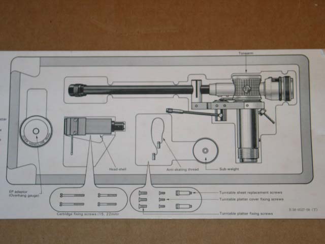
L-07D tonearm part description card shown above, identified by tonearm rest detail.
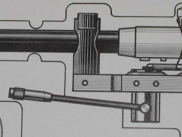
Close-up of L-07D II tonearm part description card shown above, identified by tonearm rest detail.
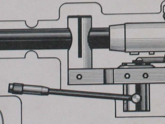
Close-up of L-07D tonearm part description card shown above, identified by tonearm rest detail.
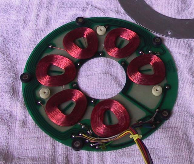
L-07D II motor stator PCB shown above. Notice that there are six separate coils which are not evenly positioned around the PCB. Hall elements are also not positioned 180 degrees apart. Three white plastic bumpers do a better job (than the earlier version) of protecting the coils from rubbing the rotor when platter is removed.
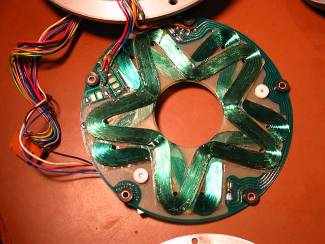
L-07D motor stator PCB shown above. Star shaped coils are continuous around the PCB. Hall elements are positioned 180 degrees apart. The L-07D PCB only has two white plastic bumpers, which do not protect the coils as well as the L07DII design, which has three of them. The most common star coil color of the first generation stator is green.
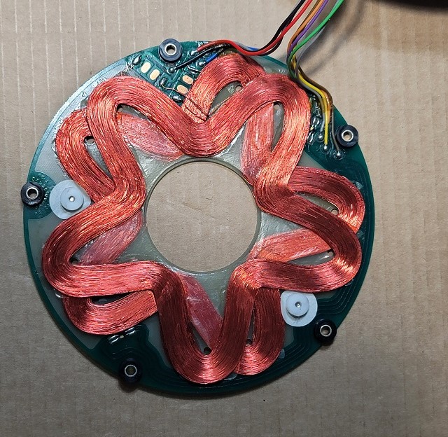
First generation L-07D stator coil with copper color star coils shown above.
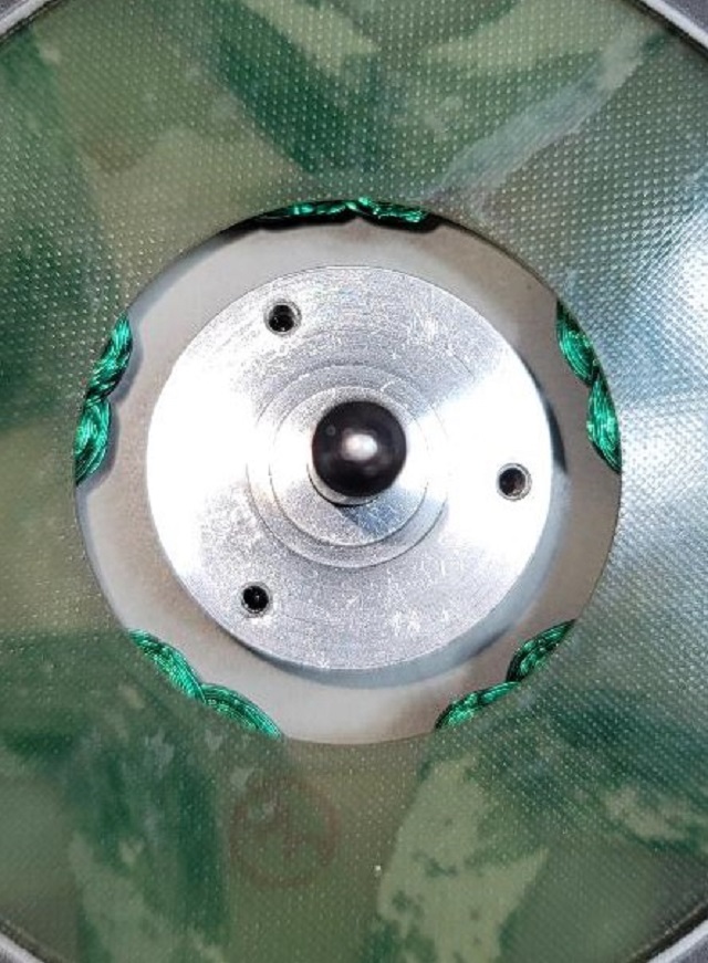
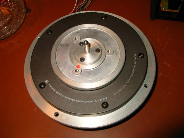
Some motor shafts had three holes for attaching the subplatter support plate with screws as shown above. All three of the holes are threaded to accept screws.
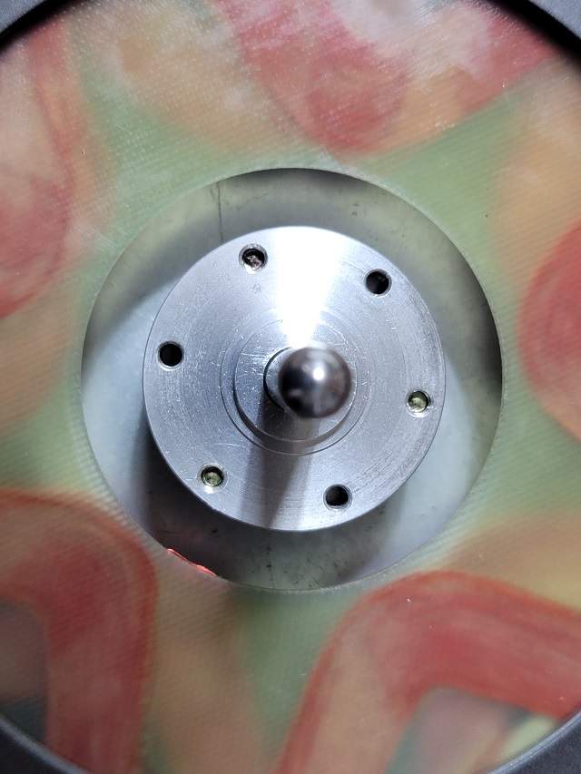
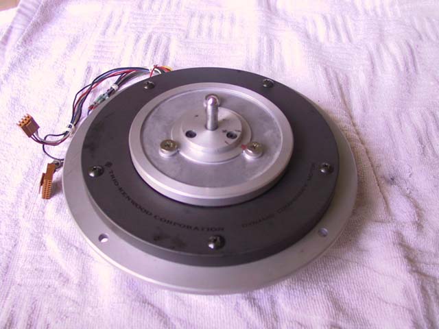
Some motor shafts had three holes for attaching the subplatter support plate with screws, and three other non-attachment holes for a total of six, as shown above. Only three of the six holes are threaded to accept screws.
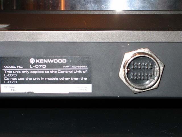
L-07D II rear connector shown above
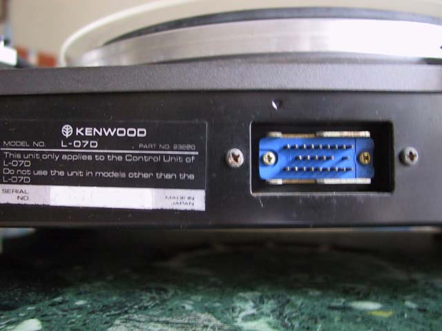
L-07D rear connector shown above.
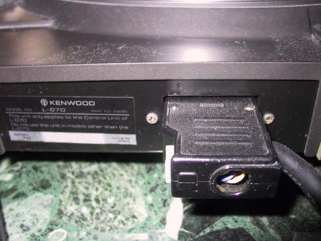
L-07D II Rear Connector, with Control Unit Cable attached, shown above.
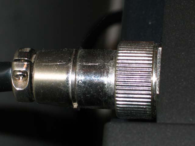
L-07D rear connector, with Control Unit Cable attached, shown above.
L-07D II Logic PCB with white PH-1 and PH-3 male connectors on the right side of the picture above.
L-07D Logic PCB with orange PH-1 and PH-3 male connectors on the right side of the picture above.
The L-07D II Transitional Model
It appears that at least one deck was made with L-07D II footers, but without the L-07D II tonearm rest or rear connector. The L-07D II footers did not have a replacement part number, so it is unlikely that the deck shown below had the footers changed by the owner.
![]()
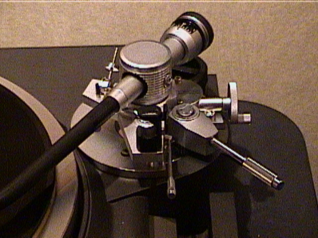
Transitional deck shown above with L-07D style tonearm rest and rear connector, but with L-07D II style footers.
![]()
Side view of transitional deck shown above with L-07D style tonearm rest and rear connector, but with L-07D II style footers.
![]()
Close-up side view of transitional deck shown above with L-07D style tonearm rest and rear connector, but with L-07D II style footers.
Regional Variations
Units sold in the U.S.A. were single voltage units made for 120 VAC operation only. Both the Control Unit and the Turntable were labeled with two stickers found on U.S.A. only models. One sticker read: "CAUTION - To prevent electric shock, do not remove any screws. No user-serviceable parts inside. Refer servicing to qualified service personnel." The other sticker read: "UL listed audio equipment."
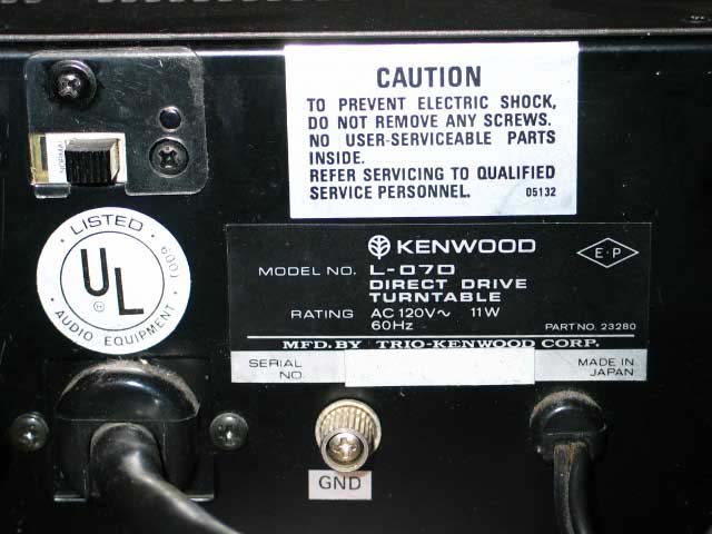
The U.S.A. model Control Unit rear plate shown above. Input voltage is not adjustable. Note attachment point of U.S.A. style connector cord at bottom left of picture which has a more robust mounting than the worldwide model shown below. The power cord is fixed.
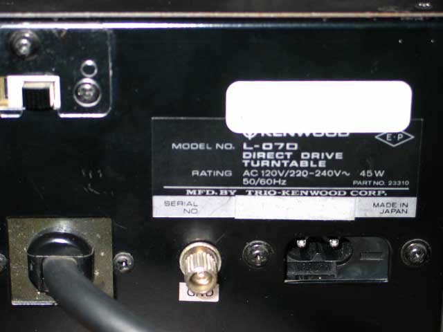
The worldwide model Control Unit shown above has dual input voltage adjustability. A slider is used to select between either 120 VAC or 220-240 VAC input voltage. The unit is set for 120 VAC operation in the photo above. The power cord is removable.
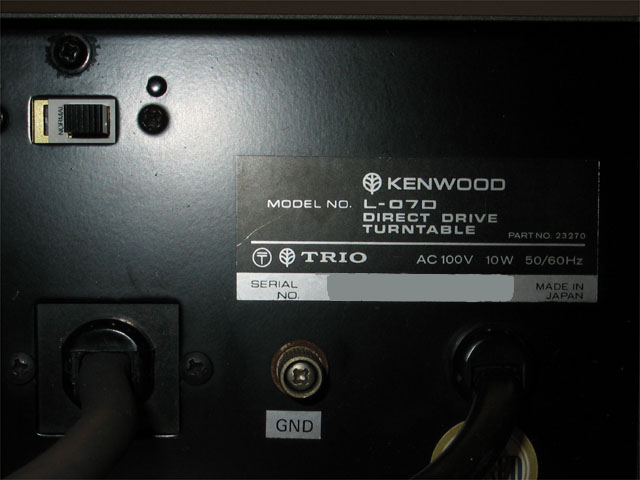
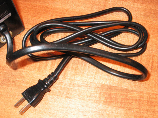
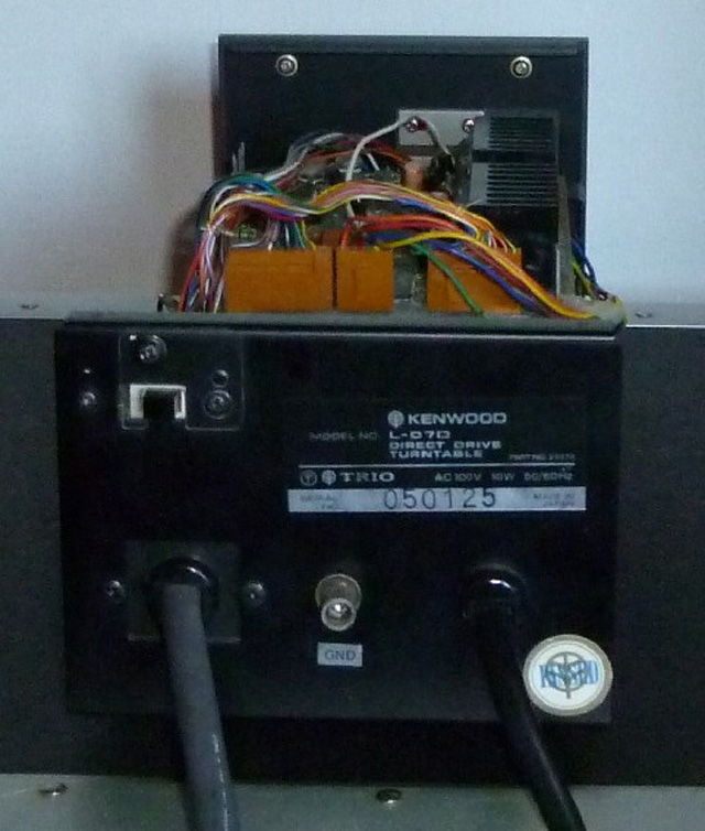
The Japan model Control Unit rear plate shown above. Input voltage is 100 VAC and is not adjustable. The power cord (close-up shown below) is fixed and thicker than U.S.A. power cord. This unit would require a 120 VAC to 100 VAC power convertor to be used in the U.S.A.
Regardless of whether unit is 120 VAC only, 100 VAC only or 120-220 VAC switchable, the PCB circuitry is the same in all Control Units. The differences between the different region Control Units is the transformer.
The main connector cable between the Control Unit and the rear connector of the turntable is a thick black cable that contains twenty internal wires. These wires terminate inside the Control Unit at the PH-1 and PH-3 connectors on the Logic PCB. These wires terminate in a large female connector on the other end, which mates to a male connector on the back of the turntable. On U.S.A. only production models, the internal wires had insulation which were all blue, and contained a very stiff, thicker, insulation. The result was a much stiffer connector cable. On worldwide production models, the main cable contains color coded wiring. The color coded insulation was very flexible. Therefore, the entire umbilical was a much less stiff cable. The author believes that the thicker insulation may have been needed to meet U.L. (Underwriter's Laboratories) approval on U.S.A. models.
U.S.A. only Control Unit cable with all-blue wires terminating at the PH-1 and PH-3 connectors seen at the right of the picture above.
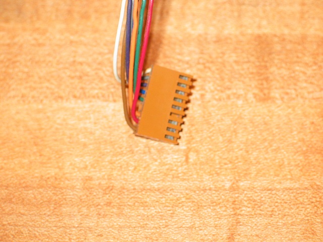
Worldwide production units had the color coded cable shown at the right of the picture above.
Miscellaneous Variations
In addition to the above variations, I have identified the following additional variations:
TDK, the manufacturer of the L-07D motor, used thin copper shims to adjust the clearance between the rotor and the stator. I have seen some motors with no shims, some with one set of shims, and some with two sets of shims. The amount of shims varied based upon manufacturing tolerances.
The DS-20 Outer Disk Stabilizer was made in two versions. The earlier version was lighter and used a round Plexiglas centering device similar in appearance to the Plexiglas platter dust cover. The later version is thicker and heavier. It uses an aluminum triangle shaped centering device.
The DS-21 Inner Disk Stabilizer was made in two versions. The earlier version was lighter. The later version was thicker and heavier. The earlier version was labeled "DS-20". (See the Accessories section of this website for further details.)
L-07D's sold in the U.K. were labeled "Trio." L-07D's sold everywhere else were labeled "Kenwood."
All L-07D's sold in the U.K. were labeled "Trio". An example is shown above.
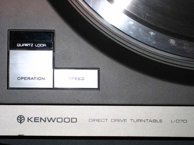
The photo above shows the front of a L-07D turntable labeled "Kenwood".
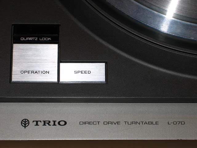
The photo above shows the front of a L-07D turntable, sold in the U.K., labeled "Trio".

The photo above shows a U.K. Control Unit on the left labeled "Trio".
Serial Numbers
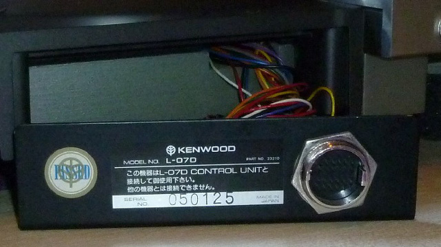
Almost all L-07D's have eight-digit serial numbers, with the rare exceptions as shown below. This unit below had the earliest version of the logic PCB shown above..
L-07D Total Production
I am sometimes asked about the total production number for the L-07D. I have contacted Kenwood Japan regarding this subject. Unfortunately, they have informed me that the production information for the L-07D has long since been discarded. L-07D's were in production from 1979 through 1982.
From my private L-07D Registry, I have been able to discern some facts, which are as follows:
All L-07D's have eight-digit serial numbers, with the rare exception shown above. The first-three-digits (the serial number “prefix”), in many cases, appears to pertain somewhat to either the country where the unit was originally sold, or to the Kenwood Headquarters where it was originally stocked. In all cases, the middle two numbers are 00. It does not appear that the last-three-digits of the serial numbers are associated with the total production of all L-07D’s as I have identified the same last-three-digit sequence in different prefix units. Also, the last L-07D’s produced were L-07D II’s. These units have lower last-three-digit numbers than many first generation L-07D’s. Therefore, it appears to me that the last-three-digits were assigned in sequence for a given first-three-digit prefix, with the possible exception of prefixes 009 and 010.
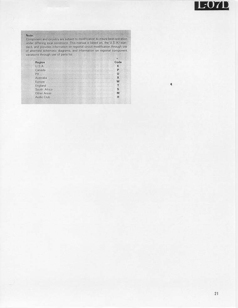
The L-07D U.S.A. Service Manual states on Page 21: “Component and circuitry are subject to modification to insure best operation under different local conditions.” Kenwood assigned nine Regional Codes in the L-07D Service Manual for part number ordering, as follows:
Region Code
U.S.A. K
Canada P
PX U
Australia X
Europe W
England T
South Africa S
Other Areas M
Audio Club H
Therefore, I surmise that there are potentially nine “Regions” for which the serial number prefixes may be associated with. Furthermore, the L-07D Service Manual listed nine Kenwood Headquarters locations. The serial number prefixes may have had some association with which Headquarters location ordered or received the particular unit.
The nine locations were:
Carson, California, U.S.A.
Secaucus, New Jersey, U.S.A.
Benensville, Illinois, U.S.A.
Zaventem, Belgium
Heusenstamm, West Germany
Paris, France
Taby, Sweden
Artarmon, Australia
Hong Kong
From the L-07D Registry, I have observed the following:
All units that were badged as Trio (for U.K. sale) have serial number prefixes of either 009, 111 or 204.
All units that have prefixes of 301 are Kenwood L-07D II’s.
Prefixes 009, 010, 011, 101, 111, 204 are units that were sold primarily in Europe.
Most U.S.A. units have a prefix of 106.
From the L-07D Registry, I have been able to identify the following serial number prefixes (first-three-digits), and the range of last-three-digit serial number units in the registry per each corresponding prefix:
009 013 to 480
010 337 to 344
011 024 to 037
050 125 to 175
101 009 to 018
106 002 to 342
111 002 to 118
204 014 to 143
209 055
301 054 to 057
Total L-07D production remains a mystery. However, if I add up the highest last-three-digit number from each of the ten prefixes in the L-07D registry I come up with a sum of 1769 units.
If you own an L-07D not already registered, please contact me so that I may add it to the Worldwide Private L-07D Registry.
All trademarks and rights belong to the OEM and are reproduced here for information purposes only. Copyright © 2003-2022. All rights reserved.