![]()
![]()
![]()
![]()
![]()
![]()
![]()
![]()
![]()
![]()
![]()
![]()
![]()
![]()
![]()
![]()
![]()
![]()
![]()
![]()
![]()
![]()
![]()
![]()
![]()
![]()
![]()
![]()
![]()
![]()
Servicing and Repairs
The L-07D instruction manual recommends having the deck serviced every two years. Neither the instruction manual nor the service manual specify what is to be done at routine servicing. From the service manual, I can surmise that routine service would involve trim pot adjustment on the logic card with an oscilloscope to set Phase Lock Loop parameters at start-up and run conditions. Next, trim pots are adjusted to set positive and negative peak voltages of the sine wave driving the motor at equal values. The last trim pot set is the one affecting wow and flutter, which requires an oscilloscope, a wow & flutter meter and a suitable test record. The procedure is covered on page 13 of the L-07D service manual and on page 9 of the L-07D II service manual.
The only other issue for routine service is motor bearing lubrication. According to the instruction manual: "The motor used in this turntable is of the lubrication-free type." Having serviced many L-07D motors, I can now say that bearing lubrication should be given careful attention. More than half of the bearings that I have inspected were either dry or running on fumes. The remainder had some dirty oil that had thinned out and had become contaminated after more than 20 years of use. Therefore, I recommend that any L-07D that has not had the motor serviced recently should have the bearing/thrust plate cleaned, inspected and re-lubricated. I recommend Redline pure synthetic 20 weight racing oil. Nothing else I have tried comes close to the pitch perfect sound and silent bearing running I have heard with this oil in the L-07D bearing. An oil change should be good for six years. As for the motor electronics, the wiring is checked, especially the solder points of the motor wiring to the PCBs, inside the motor. The Stator coils are checked for bare spots and short circuits, and repaired & touched up with lacquer if any are found. The resistances of the Hall elements are checked. The Hall elements are replaced if the resistances are out of spec and/or if wow and flutter are out of spec and the fault is traced to the motor.
Repairs involve identifying and correcting the fault(s) and adjusting the deck to factory specs.
Restoration involves a replacement of all Control Unit capacitors, power supply rectifiers, and power supply transistors, and motor overhaul. This is the route that I recommend be taken to ensure stable long term operation. I always use better than factory spec components in my restorations.
Basically, OEM parts are no longer available for this deck. I have stockpiled some parts, and I can offer repair services long into the future. Most of the electronic components in the L-07D are readily available from major electronic components vendors, some of which are listed on this site's Links page.
In my opinion, a fully restored L-07D will likely sound better than a new L-07D, as the electronics are upgraded, a better bearing oil is used, and the adjustment procedure I use is refined beyond factory recommended methods, particularly with wow and flutter adjustment.
I have serviced many of these now, and I believe that most any fault(s) can be repaired.
The pictures below highlight some of my repair experience with this marvelous deck.
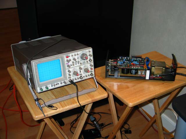
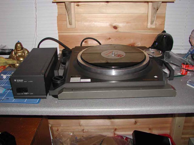
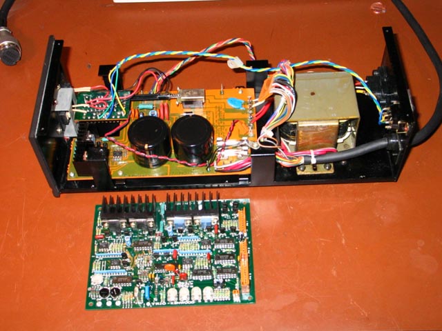
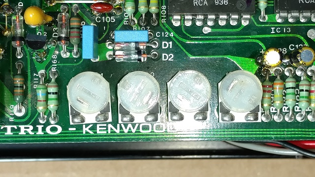
Oscilloscope and Control Unit shown above. The power supply PCB is the lower PCB and the Logic PCB is the upper PCB in the Control Unit. The robust transformer is seen at the rear. The power supply in this unit is as-original. The large black caps are 10,000 uF 35V power supply electrolytics. More so than other components, capacitors can change values and/or totally fail, causing many problems.
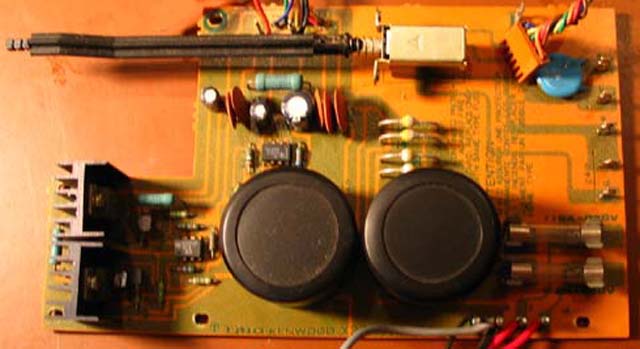
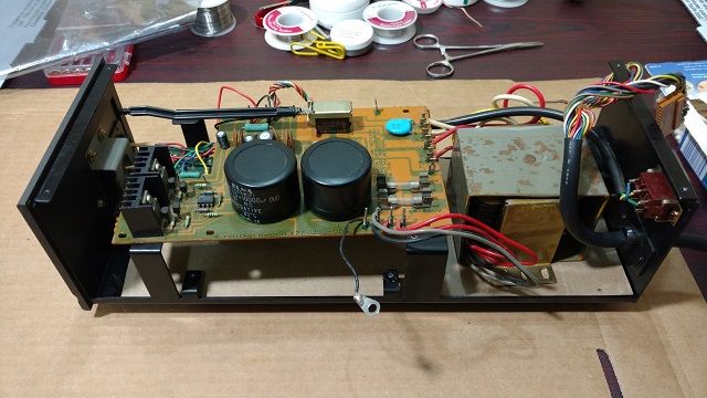
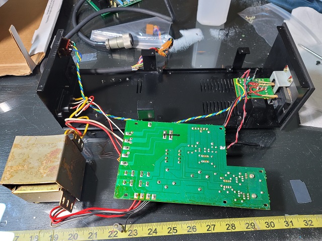
The picture above shows the power supply as-original, outside the Control Unit.
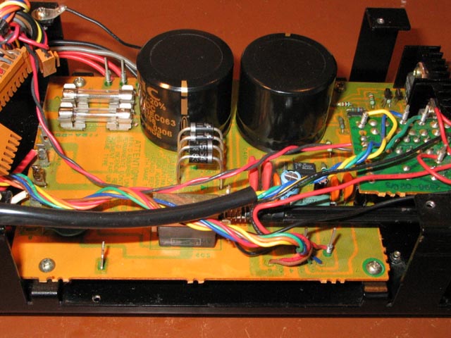
Rebuilt power supply in the Control Unit shown above. The large black capacitors are BHC 10,000 uf 63V four prong electrolytics from the U.K. (Kemet has bought out BHC. The same capacitors are available from Kemet.) They are rated at 18,000 hours of use. High-speed high-voltage epoxy rectifiers are used to replace the original glass rectifiers. The small caps and power transistors are upgraded as well.
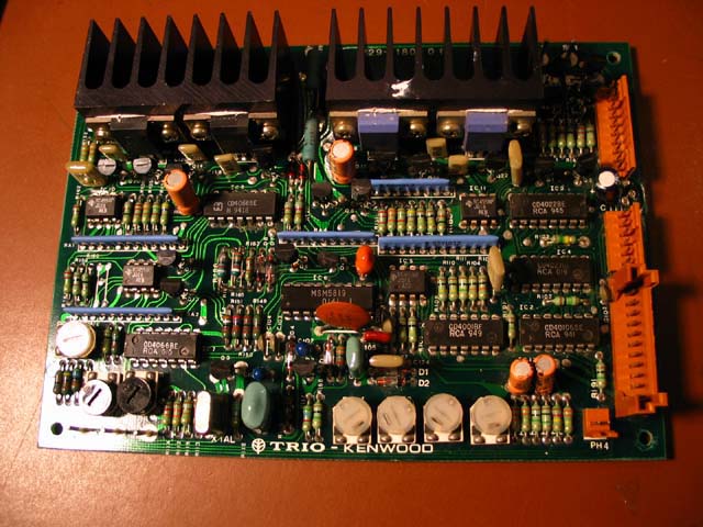
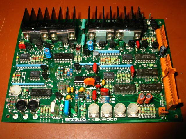
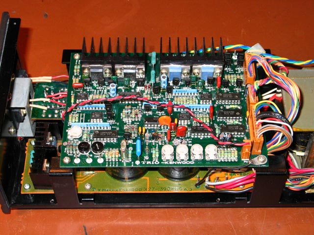
As-original Logic PCB shown above.
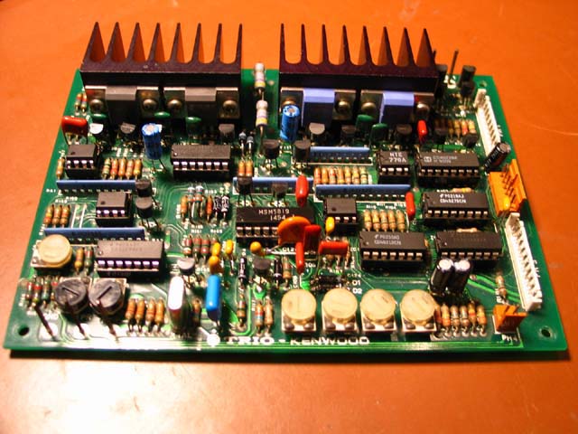
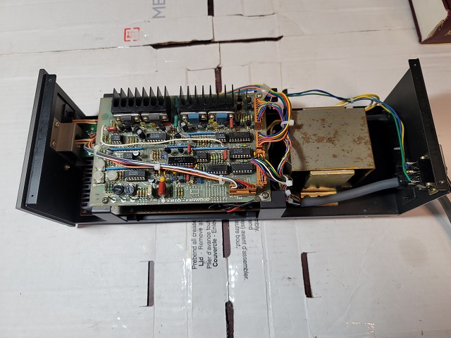
Restoration of a working Logic card with all new (26) capacitors shown above.
This PCB (above) was badly damaged by a short circuit (bad soldering by a prior technician). Restoration required replacing everything, except the resistors which were fine. All transistors are new, as are the capacitors and diodes. All 11 IC's were replaced, using low profile sockets. This PCB was once in a set written off as scrap. Now the owner in Singapore can enjoy his L-07D II again daily.
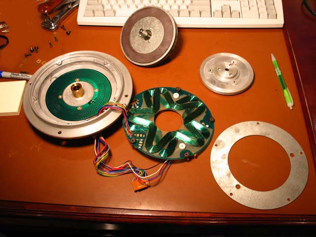
Properly disassembled L-07D motor shown above. There are definitely some "do's and don'ts" when disassembling and reassembling the motor. (See further down on this page.)
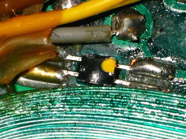
A bad Hall element shown above.
.
New Hall element shown above on Stator PCB.

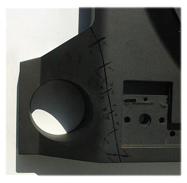
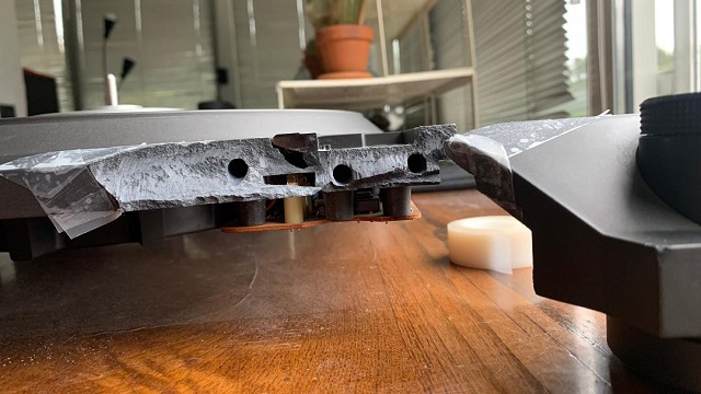
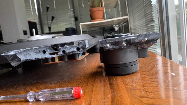
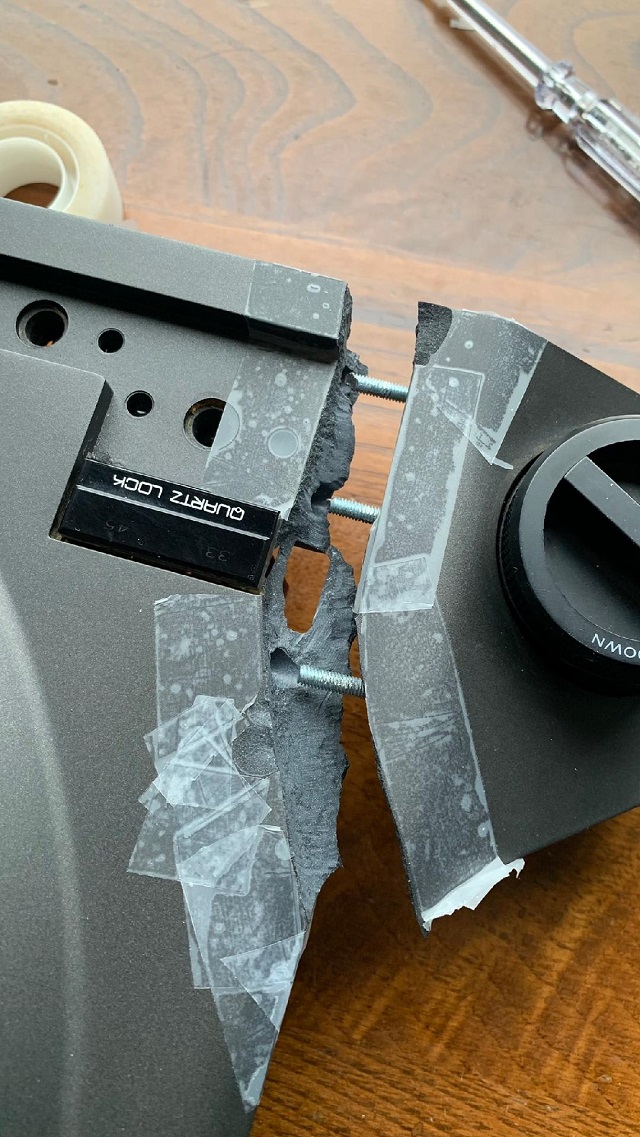
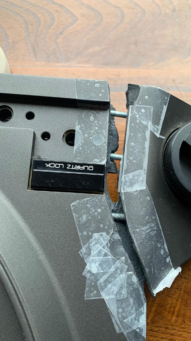
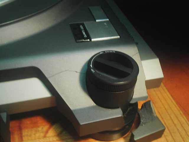
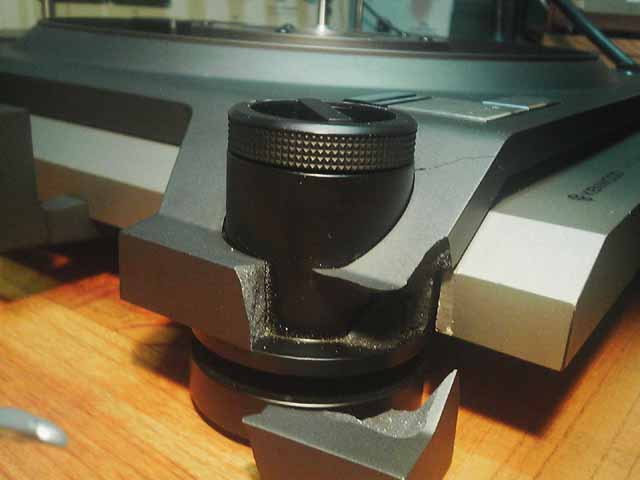
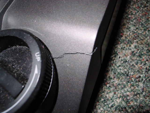
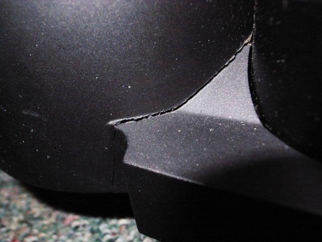
Cracked Plinth shown above.
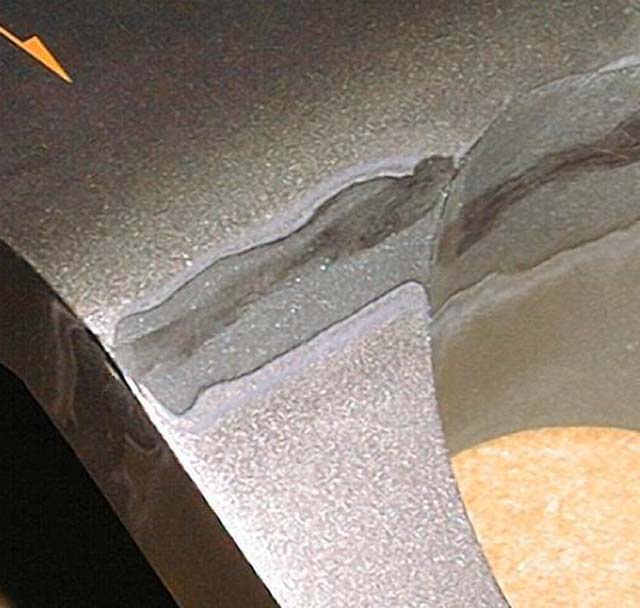
Repair in progress shown above. Repair effected with internal steel pegs, epoxy, careful surface finishing and paint matching.
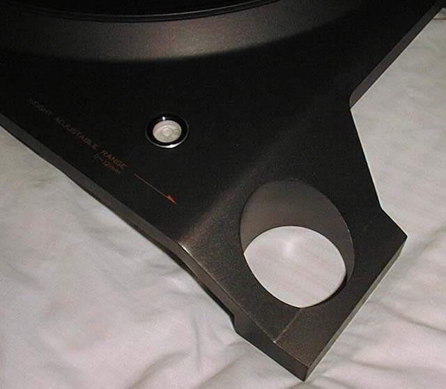
Perfect repair completed shown above. The plinth repairs were performed for me by Vantage Audio in the U.K.
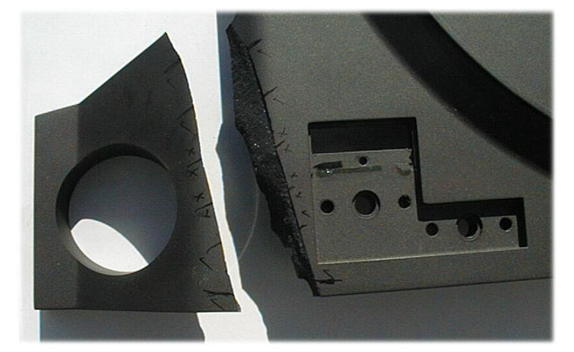
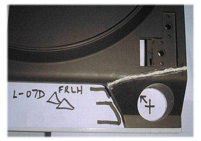
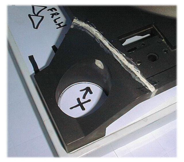
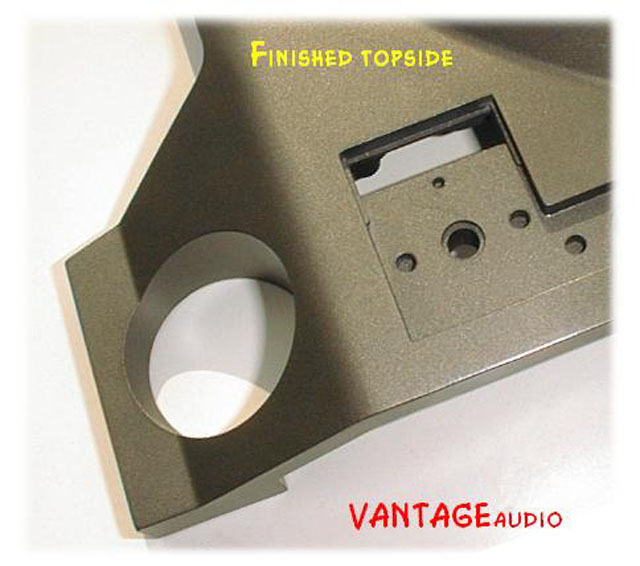
Another excellent plinth repair performed by Vantage Audio in the U.K. shown in the pictures above.
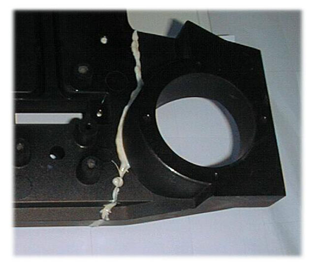
Another excellent plinth repair performed by an L-07D owner shown in the pictures above.
The photo above shows a rotor magnet that was sheared from the base plate, as viewed from the top of the rotor. The magnet is now severely off center within the motor. This motor came to me for repairs from a set that suffered a cracked plinth during shipping. Perhaps the same event that caused the cracked plinth did this damage to the motor.
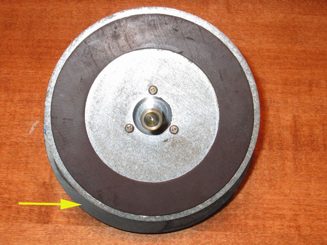
The delaminated shifted rotor magnet (yellow arrow) as viewed from the bottom of the rotor.
Rotor magnet centered, aligned and re-bonded to base plate.
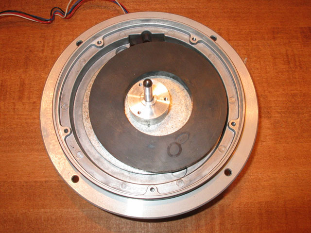
The photo above shows a rotor where the FG induction magnet has de-bonded from the base plate.
The de-bonded FG induction magnet shown above.
Rotor FG induction magnet centered, aligned and re-bonded to base plate.
This poor Trio has suffered multiple mishaps. First it fell from a shelf landing on the spindle. The result was a bent rotor shaft and thus a wobbling platter. It ended up on eBay. As a result of shipping damage while in-transit to the high bidder, the right front corner of the ARCB plinth and one footer were lost.
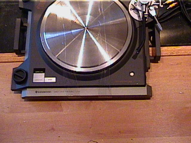
Close-up of broken plinth shown above. The stainless steel platter sheet has gone missing.
The deck above sat dormant in a home in Yugoslavia. Bought from Germany, it never worked properly for the owner in Yugoslavia. Note the black crinkle-paint applied to the front of the sub-plinth. The fault was found by me to be a bad Hall element in the motor.
All four footers on the Yugoslavia deck were cracked and painted with the same crinkle-paint as the sub-plinth, as shown above.

Corroded platter sheet from Yugoslavia deck shown above.
From two bad decks, one good one is saved and fully restored. Control Unit and sub-plinth are from the Trio. ARCB plinth, motor, platter sheet, tonearm base and tonearm are from the Yugoslavia deck. Meticulously cleaned and polished. All electronics were rebuilt and the motor fully serviced. N.O.S. footers completed the restoration! Also of possible historical value, as this "Trio" has serial numbers of one of the first few L-07D's ever built.
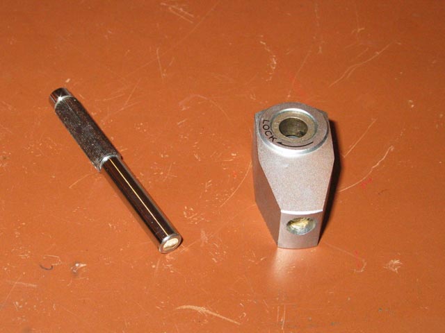
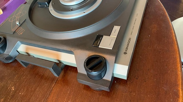
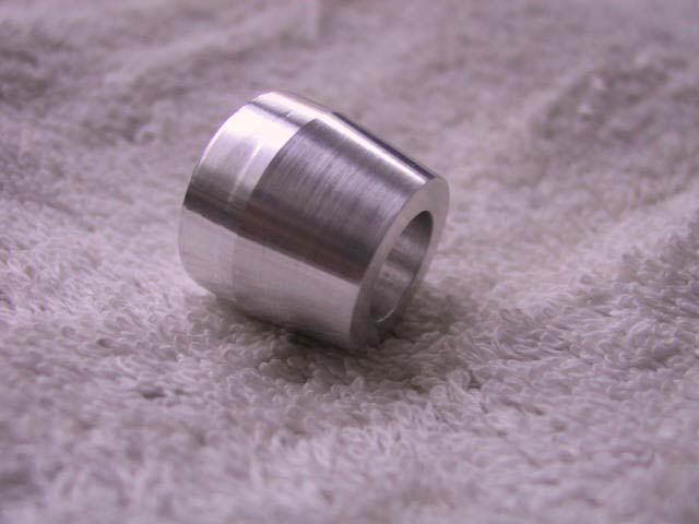
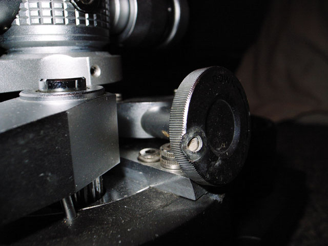
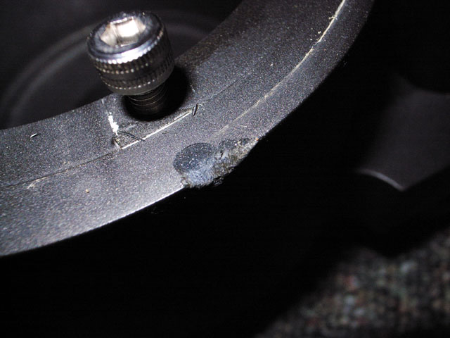
A not-uncommon malady on the L-07D is shown above. The threaded section of the Collet-chuck handle is brass, and can fatigue with heavy use.
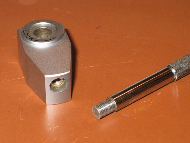
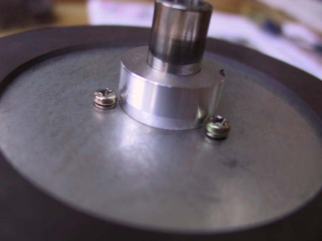
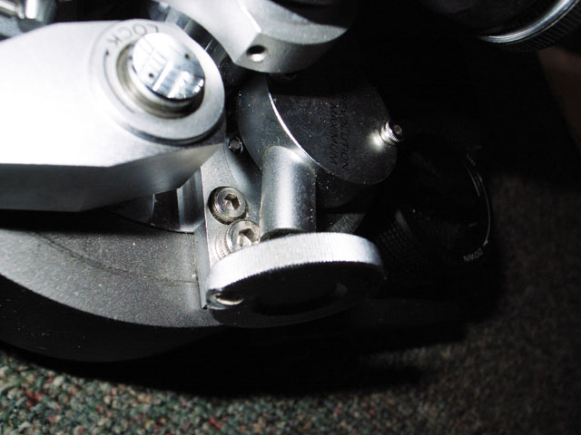
Broken brass stud extracted and replaced with a steel threaded exact replacement stud.
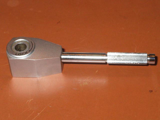
Perfect!
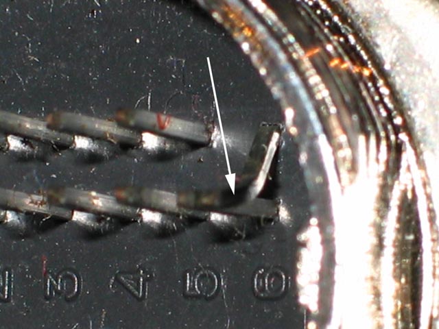
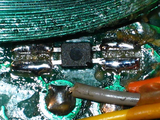
A bent rear connector pin (see arrow above) can cause serious problems!
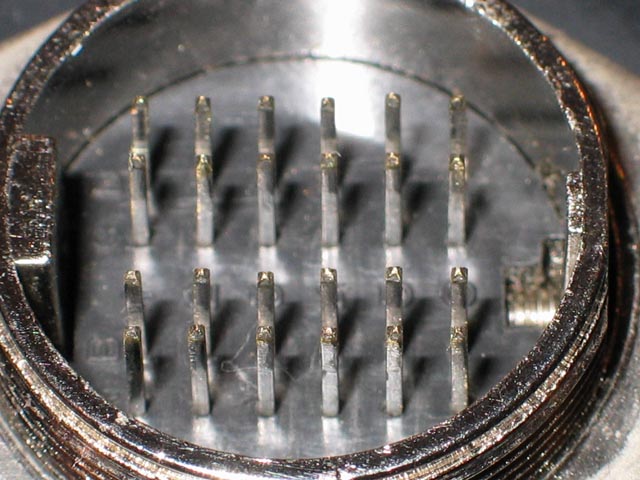
Bent pin straightened and corrosion cleaned from all pin contacts, in photo above.
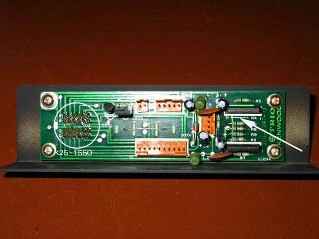
A deck with intermittent quartz lock problems at 33 rpm had the problem isolated to the Rear Connector PCB. The main fault was a missing (see arrow above) R4 680K resistor! Apparently a manufacturing goof! Long term operation without the resistor resulted in a damaged IC 201.
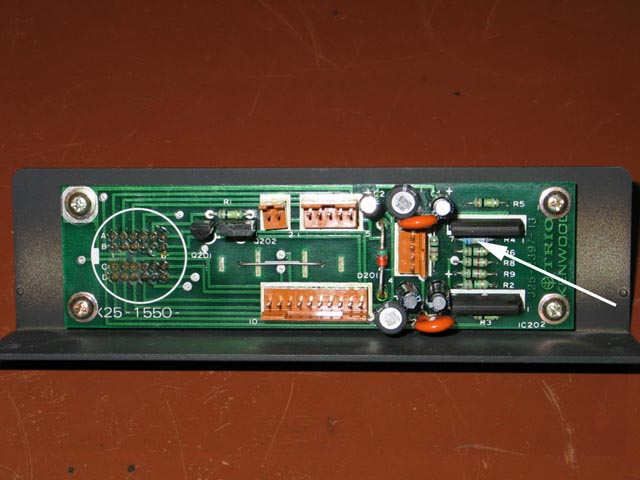
The same Rear Connector PCB rebuilt with upgraded capacitors and inductors. The two IC's and both transistors were also replaced. The arrow shows the missing R4 resistor installed where it belongs. Now this PCB works properly.
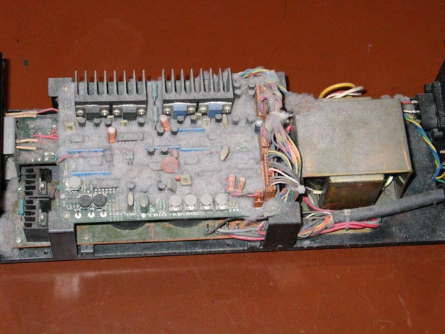
Control Unit that apparently has served duty as a "lint-catcher" is shown above.
Debris everywhere, as seen above
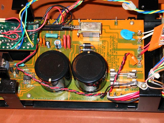
Entire Control Unit is now spotless and rebuilt. Rebuilt power supply PCB shown above. New robust capacitors, high speed-high voltage rectifiers and....
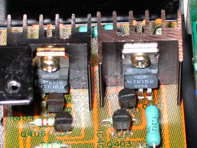
NTE power transistors shown above - better than original!
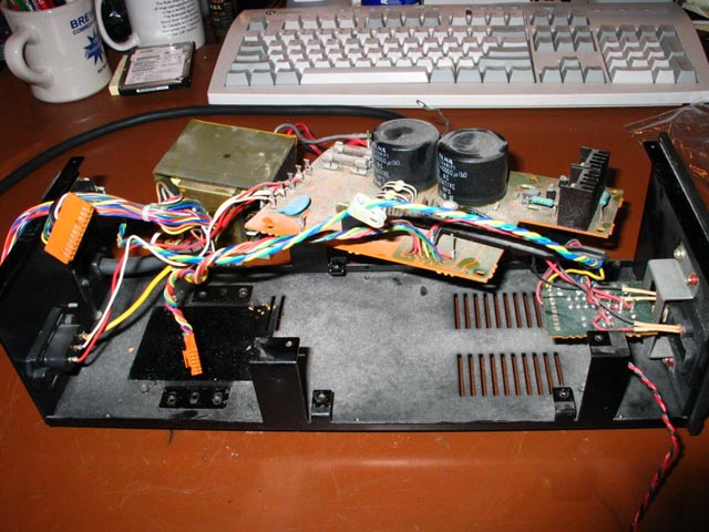
Reassembly in progress, shown above.
Internally reassembled unit shown above. All caps on the Logic PCB are new and upgraded.
Rebuilt Control Unit shown above with very early style logic PCB.
A 12cm x 32cm sheet of single layer cardboard is used temporarily during the power supply rebuild above. The cardboard sheet is inserted after cleaning the floor of the control unit to protect the floor of control unit from scratches during the power supply rebuild. The carboard is removed after the power supply rebuild before securing the power supply PCB and transformer back to the control unit with screws.
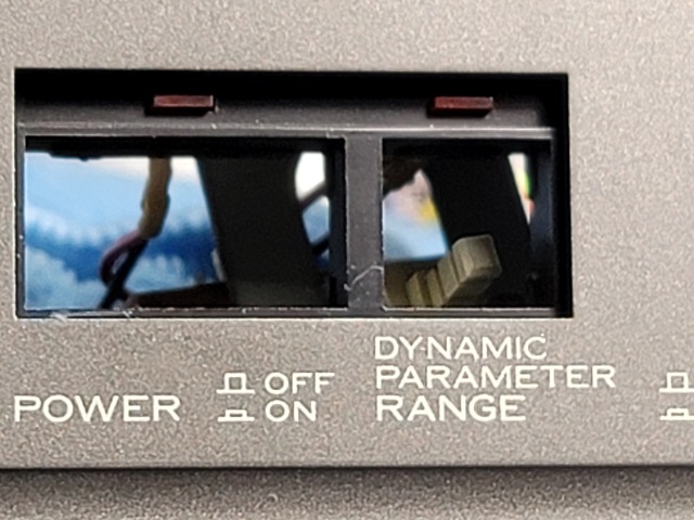
Repair of de-bonding of LED panel from inside Front Panel of the Control Unit
The plastic panel around the front two push-switches that holds the LEDs was glued to the inside of the front panel of the Control Unit during manufacture. The original glue can become de-bonded and require repair. I re-glue with cyanoacrylate holding for 10 minutes or so and then let cure overnight before reassembling the Control Unit. Some original glue remaining on the Control Unit side and some on the plastic panel side of the original glue bond each have surfaces that will interdigitate allowing the panel to be glued back in place in perfect original position. Photos of the repair steps below. I use a piece of cardboard on the inside bottom of the Control Unit during repairs to prevent scratches to the inside bottom of the Control Unit.
Control Unit Adjustments - The Author's Method in 2022
When the service manuals for the L-07D and L-07D II were written around 40 years ago, digital storage oscilloscopes were not yet invented. The digital storage oscilloscope (DSO) was invented in 1985. So nowadays we have DSO's and other instruments available for Control Unit adjustments.
Oscilloscope: Measures in the Voltage vs. Time domain.
Spectrum Analyzer: Measures in the Frequency vs. Voltage domain.
Modulation Domain Analyzer: Measures in the Frequency vs. Time domain.
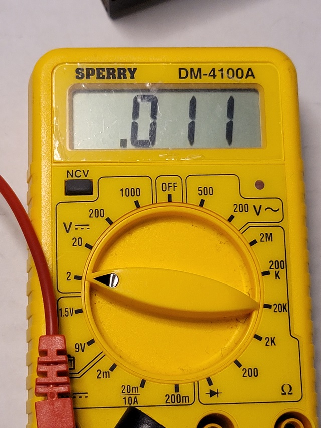
For adjusting Offset during Playback at 33rpm and at 45 rpm, I have found what I feel is a better method for adjusting Offset during Playback than the service manual method. To adjust offset during playback I like a slow acquisition-time multimeter. Slow is good here because the readout changes just fast enough that you can visually see the max + and max - voltages. I use a SPERRY DM-4100A and it works well for this purpose.
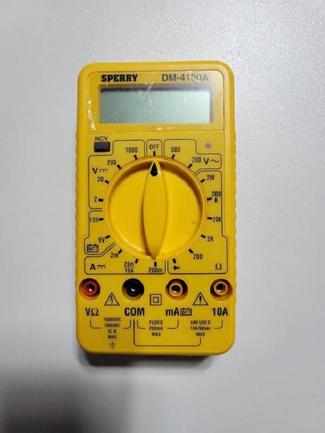
I adjust Offset during Playback with a slow acquisition-time multimeter (I use the one shown directly above). I connect the black/negative wire (with an alligator clip termination on the sampling end) from the DMM to the same ground point that the service manual shows connection to for the ground wire of the oscilloscope probe (GND). I connect the red/positive (with an alligator clip termination on the sampling end) from the DMM to SC-1 on the logic/control board when setting Offset during Playback at 33 rpm. I connect the red/positive (with an alligator clip termination on the sampling end) from the DMM to SC-2 on the logic/control board when setting Offset during Playback at 45 rpm.
I adjust Offset During Playback with the slow acquisition-time multimeter giving readouts during platter operation. The adjustment trim pots for this parameter are BO-1 for 33 rpm and BO-2 for 45 rpm. As an example, I would see continually changing numbers on the readout of the multimeter such as (for example purposes only): +16.1, +11, +5, 0, -5, -11, -15.8, -11, -5, 0, +5, +11, +16.1 etc. repeatedly (offset at playback needs adjustment in this example because +Vmax is +16.1 volts and -Vmax is -15.8 volts). In this example, I would then adjust to get: +16.1, +11, +5, 0, -5, -11, -16.1, -11, -5, 0, +5, +11, +16.1, etc. repeatedly. I am adjusting to get equal +Vmax and -Vmax. Offset during playback trim pots (BO-1 for 33 rpm and BO-2 for 45 rpm) sets the maximum negative voltage of the sine wave driving the motor.
The service manual procedure demonstrates how to set +Vmax and -Vmax for Offset during Playback at 33 rpm and at 45 rpm using an oscilloscope. I have much experience with this method. What makes this method somewhat difficult in practice is that as you watch the sine waves move along the oscilloscope screen, there are some variations in the +Vmax and -Vmax voltages of each individual sine wave. Therefore I prefer an averaging method, such as the one described above.
I generally leave the trim pots for Offset during Startup at 33rpm and at 45rpm alone, unless there is a problem.
For adjusting SC-1 GAIN which is the "wow and flutter adjustment" trim pot, one should first understand what this trim pot does. It varies the gain of the op amp that generates the signal for motor Coil 1 (also known as Coil A). So in effect, adjusting the SC-1 GAIN trim pot varies the gain of, and allows the balancing of, the signal of the Coil 1 (also known as Coil A) and the Coil 2 (also known as Coil B) motor coils against each other - so the coils are not working against each other, resulting speed instability. Motor speed is optimally stable when both motor coils have balanced gain.
The problem with simply using a test record and a wow and flutter meter to measure speed stability of the L-07D is that the accuracy of this method is limited by how perfectly centered the test record spindle hole is and test record flatness. The speed stability of the L-07D is better than the testing limitations of the test record method. With the test record method, what is being measured is the combination of turntable speed stability and test record method physical inaccuracies. Nowadays we have other digital measurement instruments that can measure motor speed stability directly from motor speed feedback from the FG windings. The measurement point in the Control Unit for this is at TPF. By measuring off motor feedback data of motor speed, the inaccuracies of the test record method are eliminated.
The FG windings are on the bottom of the motor, on the other side of the rotor magnet from the motor drive coils. The FG coils do not drive the motor. The spinning magnet rotor generates a square wave in the FG coils which can be sampled at test point TPF in the Control Unit logic/control board.
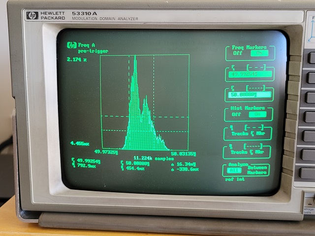
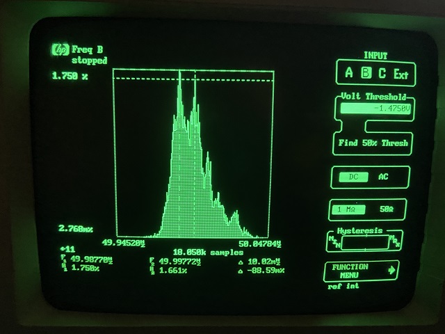
The FG signal output at 33rpm is a 50 Hz square wave which is measured at TPF. Using a Modulation Domain Analyzer (MDA) such as an HP or Agilent 53310a, which measures frequency vs. time, viewing the MDA readout during playback while sampling from test point TPF on the logic/control board shows the individual contributions of the two individual motor coils (Coil 1 and Coil 2).
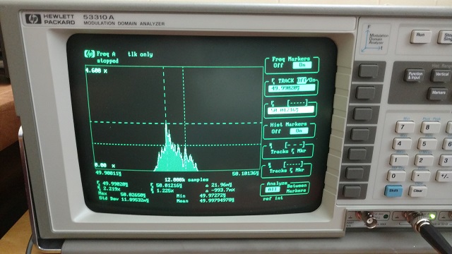
In the MDA photo above, sampling at TPF on the logic/control board at 33 rpm with the SC-1 GAIN trim pot set to minimum gain, we see that the frequency generated by motor Coil 2 (also known as Coil B) dominates.
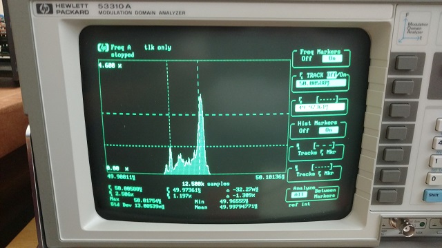
In the MDA photo above, sampling at TPF on the logic/control board at 33 rpm with the SC-1 GAIN trim pot set to maximum gain, we see that the frequency generated by motor Coil 1 (also known as Coil A) dominates.
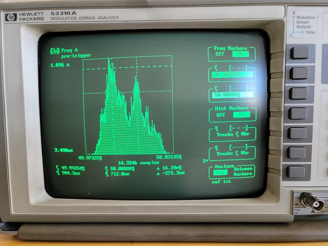
In the MDA photo above, a Control Unit that I electronically rebuilt with SC-1 GAIN setting unchanged from before the rebuild, and out of adjustment.
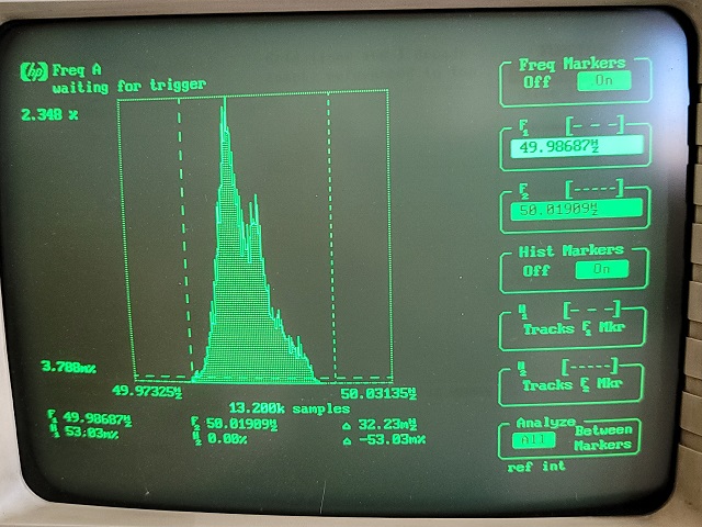
In the MDA photo above, the first adjustment made, decreasing SC-1 GAIN.
In the MDA photo above, the next adjustment made, decreasing SC-1 GAIN a bit more.
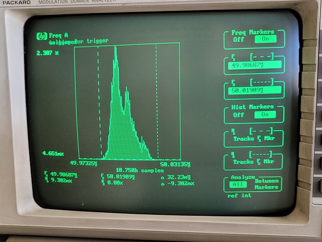
In the MDA photo above, the next adjustment made, decreasing SC-1 GAIN a bit more. Getting closer to a single peak.
In the MDA photo above, the next adjustment made, decreasing SC-1 GAIN a bit more. Getting even closer to a single peak.
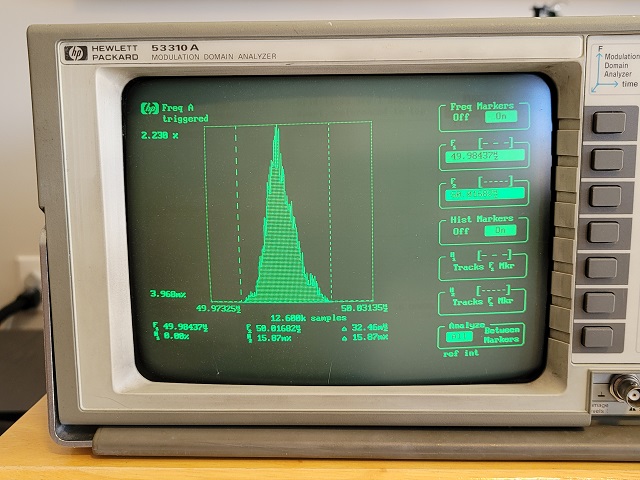
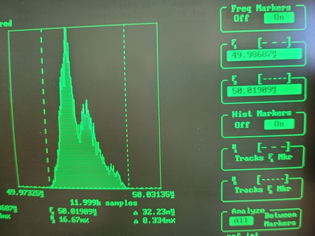
In the MDA photo above, sampling at TPF on the logic/control board at 33 rpm with the SC-1 GAIN trim pot set to final adjustment, we see that the coil outputs are adjusted so SC-1 output is dialed back just to the point where there is a single peak. Any greater output from SC-1 and a frequency peak from SC-1 will split off from the waveform. Any less output from SC-1 and the motor torque will be reduced unnecessarily.
Author's note: A "basic" HP or Agilent 53310a works fine for this purpose. You don't need one with factory options (that generally raise the price of the instrument) such as extra memory, oven crystal oscillator, extra channel, or other options.
Options for adjusting SC-1 GAIN without a MDA include using a wow and flutter meter with a test record (usually done with a 3000Hz or 3150Hz test record tone) measuring the output from one channel of the the preamplifier. Another option is using a wow and flutter meter that can measure a 50Hz signal and measuring at test point TPF on the logic/control board. My Grundig GA 1000 (German-made) "Gleichlaufanalysator" wow and flutter meter can measure signals with a frequency as low as 1 Hz.
Test records can have inaccuracies in tone frequency and how perfectly centered the spindle hole is. Such inaccuracies can affect wow and flutter measurements when using a test record with a wow and flutter meter. The DIN 545 test record is considered to be one of the more accurate test records. The DIN 545 is a 33 rpm test record consisting of multiple tracks of 3150 Hz test tones on both sides of the record from outer groove to inner groove.. All tracks on the DIN 545 test record are 3150Hz tracks.
When adjusting SC-1 GAIN based upon measurements of FG output at test point TPF on the logic/control board, you can decide if you want to take measurements without a record on the platter and therefore measurements will be with no stylus drag, or with a test record playing to add constant stylus drag.
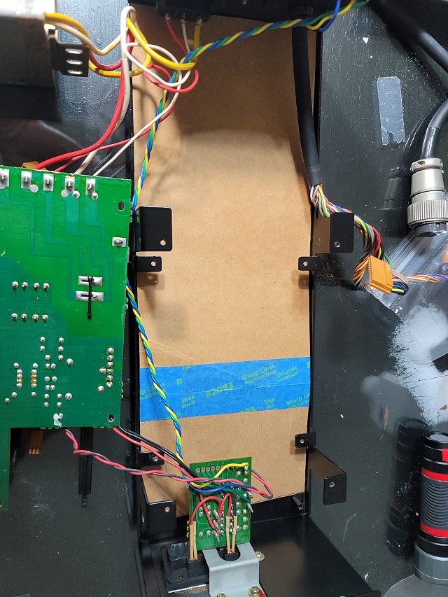
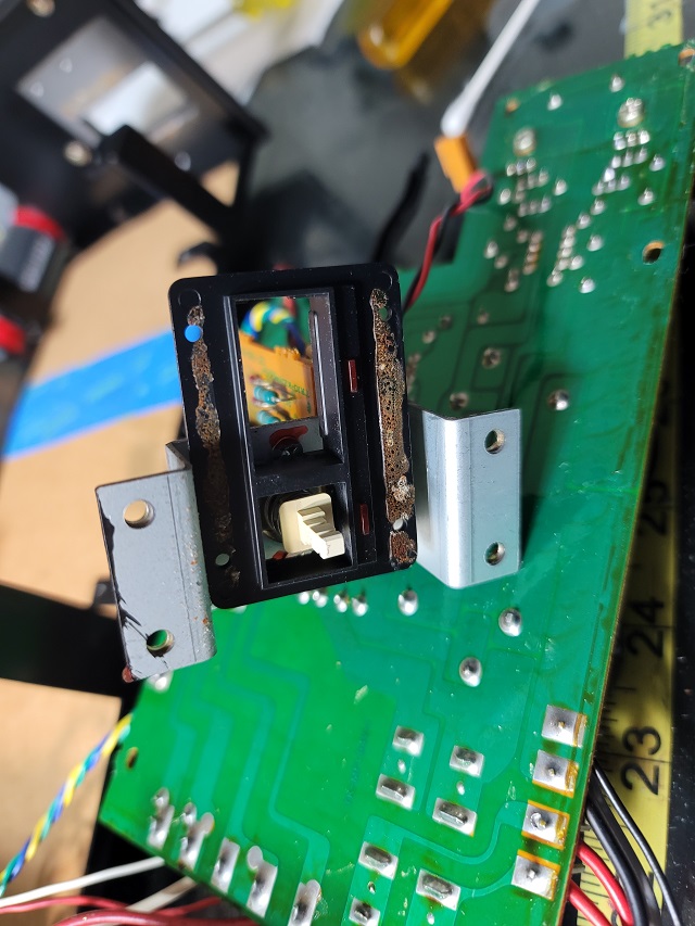
Important information about connecting the ground wire of any test instrument to the logic board for logic PCB measurements and adjustments:
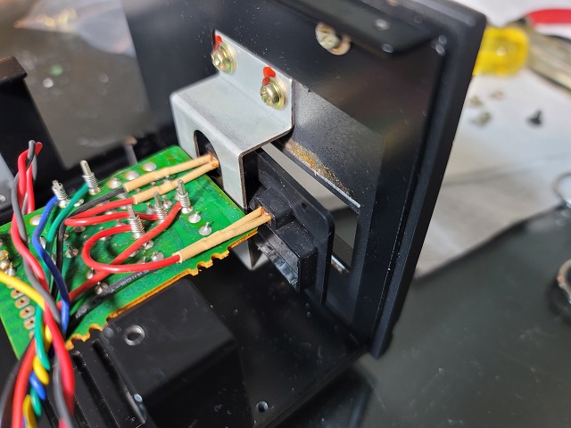
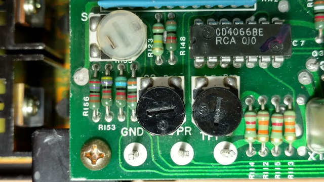
For logic PCB measurements and adjustments, only connect the ground wire of the test instrument to the GND test point of the logic PCB, and nowhere else. See photos below.
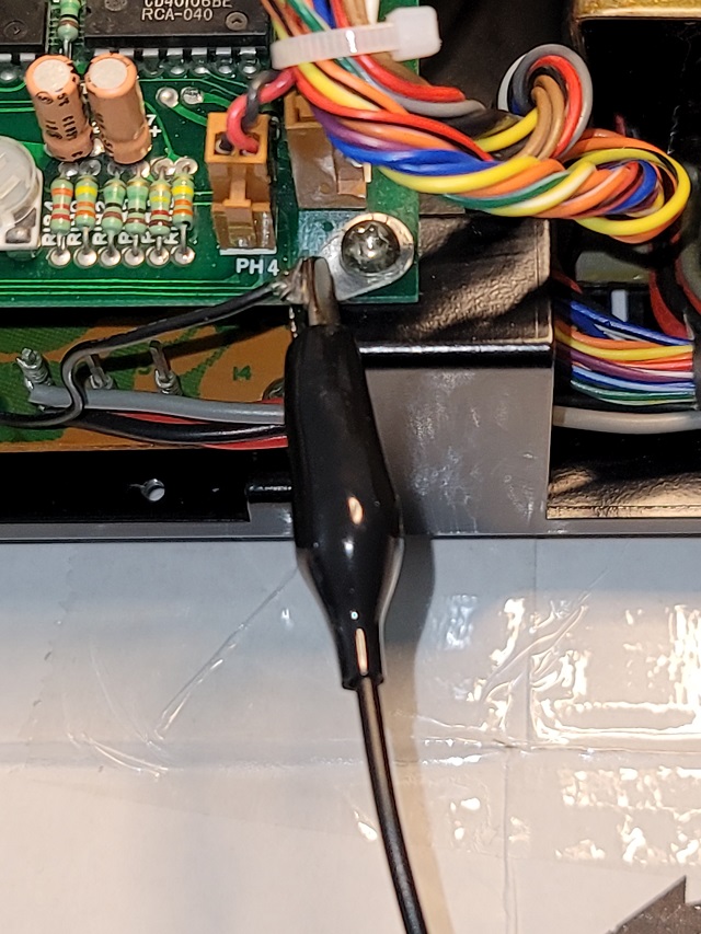
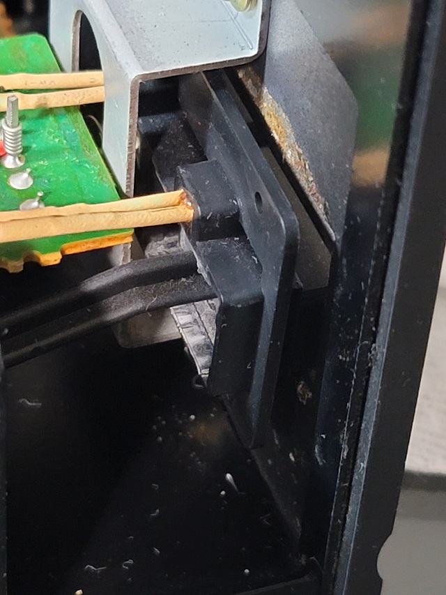
For logic PCB measurements and adjustments, never connect a test instrument ground wire to the location above. This location carries some DC as shown in the photo below.
Some DC voltage in the wire from the power supply board to the chassis. If a ground wire is connected here DC offset adjustment will be set incorrectly. For logic PCB measurements and adjustments do not connect a test instrument ground wire there! See photos below regarding where to connect a test instrument ground wire for measurements and adjustments involving the logic PCB.
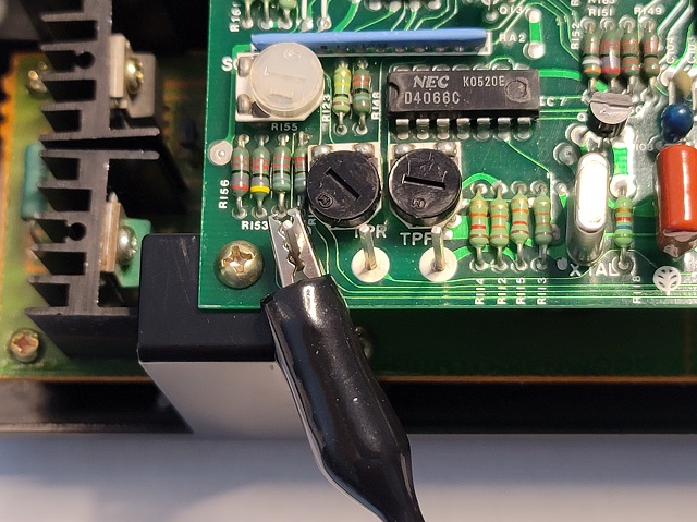
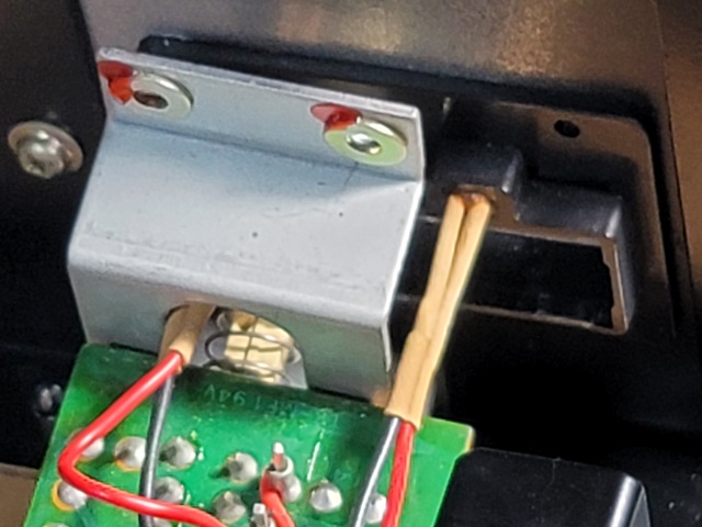
For logic card measurements and adjustments, always connect the test instrument ground wire to the GND test point on the logic card, as shown in the photo above.
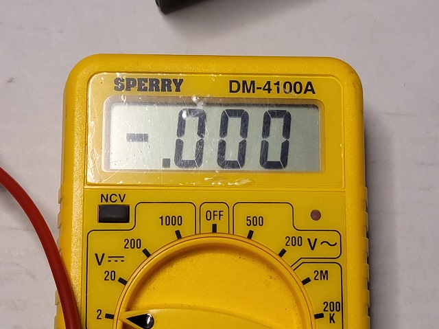
0.000v voltage at the GND test point on the logic PCB. For logic card measurements and adjustments, always connect the test instrument ground wire to the GND test point on the logic card.
**Always, always, always, each and every time without fail - always make sure the turntable is turned off and the mains disconnected before attaching or detaching any test probe or wire used for sampling from any test point in the Control Unit!! Test probes and test wires can easily short out circuitry and cause major damage!! Use immense care to prevent shorting circuitry when doing any electronic adjustments to the L-07D!!
This method is only a guide line. The author is not responsible for any damage that may be done to any part of the turntable, persons or anything else resulting from any servicing.
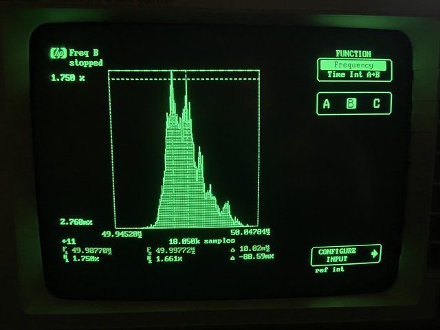
Modulation Domain Analyzer Settings for setting SC-1 GAIN
The following photos show settings for the MDA that will allow for analyzing the 50 Hz waveform when sampling at TPF on the logic PCB:
Configure Input Sub-Menu settings are shown above.
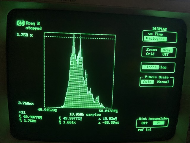
Display Menu settings shown above.
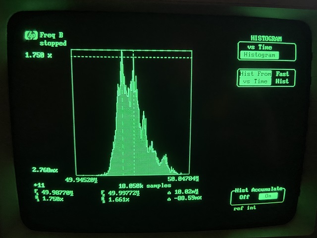
Histogram Menu settings are shown above.
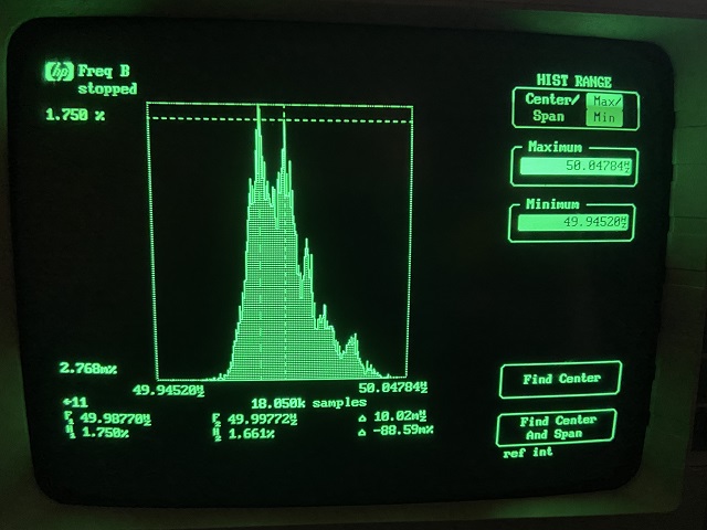
Histogram Range Menu settings are shown above.
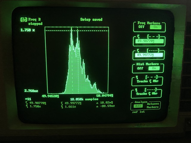
Histogram Markers screen is shown above.
Input Menu settings are shown above.
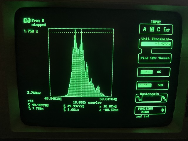
Input Sub-Menu Settings are shown above.
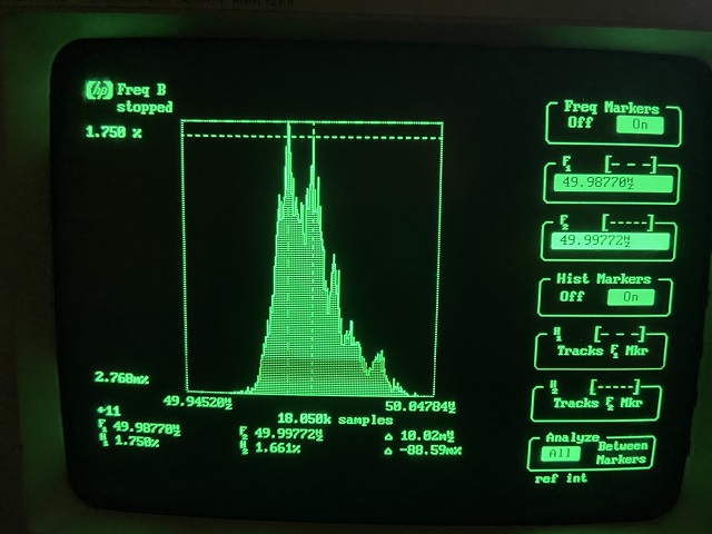
Markers menu settings are shown above.
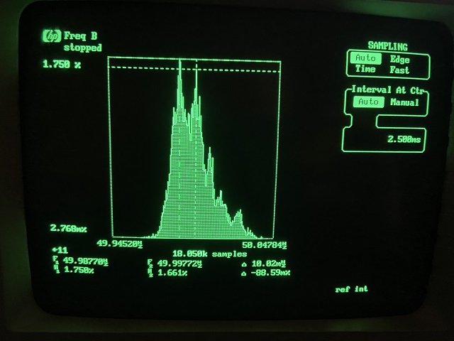
Sampling Menu settings are shown above.
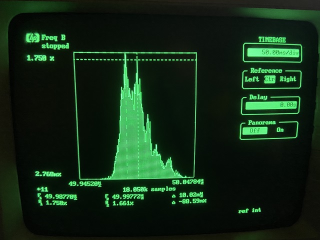
Timebase Menu settings are shown above.
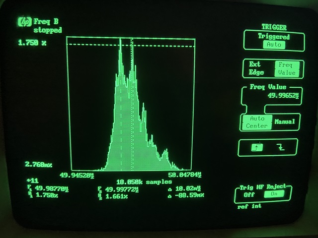
Trigger Menu settings are shown above.
This method is only a guide line. The author is not responsible for any damage that may be done to any part of the turntable, persons or anything else resulting from any servicing.
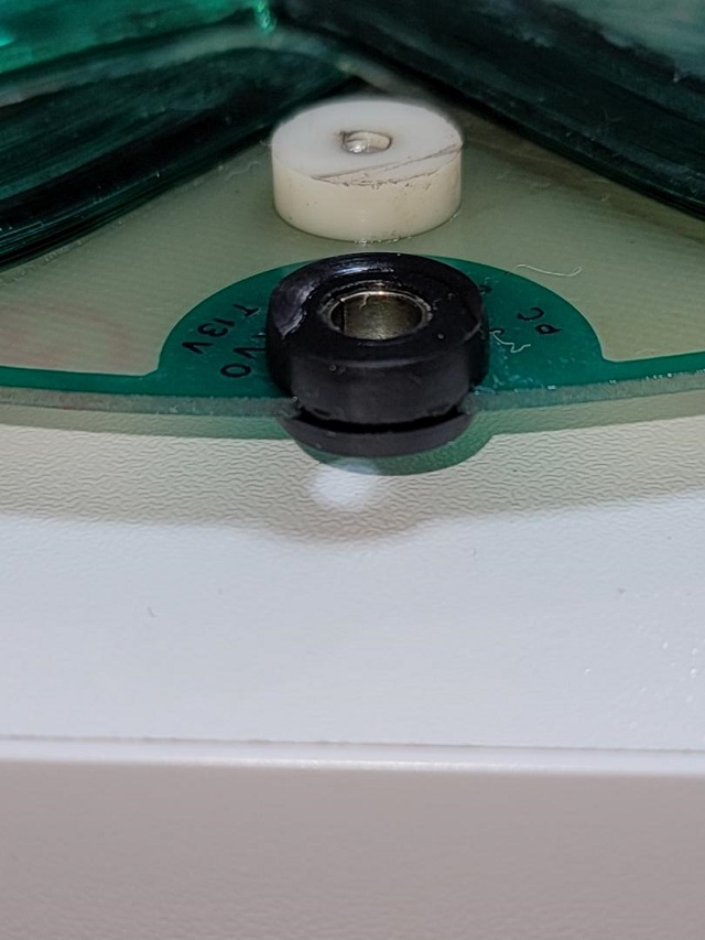
Servicing the Main Bearing
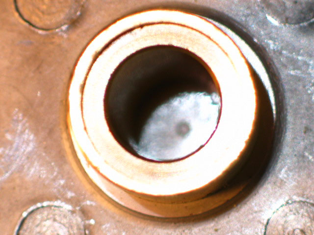
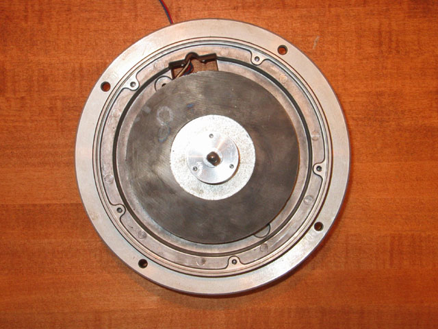
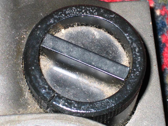
The above bearing has gone dry after twenty years. Despite the lack of oil in the bearing well, the amount of Teflon thrust plate wear is minimal as Teflon is self-lubricating. A bigger concern with a dry bearing well is metal shaft and bushing wear.
Author's Method for L-07D Motor Removal, Replacement and Bearing Lubrication
*** Read this a few times before considering doing the servicing. ***
1. Disconnect mains power cord of Control Unit from wall power.
2. Disconnect Control Unit cable from back of turntable.
3. Note VTA position from calibrations on tonearm base. Remove headshell and cartridge. Remove tonearm and tonearm cable if turntable is to be turned upside down at any time during the servicing - see below.
4. Remove platter sheet (use lifting screws) and subplatter (three Philips screws)
5. Remove tonearm base (four large hex screws) - if turntable is to be turned upside down at any time during the servicing - see below.
6. Prop turntable above work surface with two stacks of hardcover books. When going "up", insert books one-at-a-time going back and forth from side to side. This way the deck won't angle so much as to stress the footers too much while they are in contact with the turntable stand. If the deck is in the usual listening position on its turntable stand, and the turntable stand is to be used as the work surface for the servicing, then after raising the deck to the level where all four footers are just above the turntable stand, rotate the turntable and books together very carefully by rotationally sliding the books so that turntable is turned such that rear of turntable is facing 180 degrees from previous direction. Continue to add books until turntable is about 8 inches above the work surface. The footers will hang free of the books. The books will support the underside of the turntable carrying handles between the footers. Ensure that the turntable is stable and can not be tipped over or displaced. Add supports under the footers as necessary for complete safety.
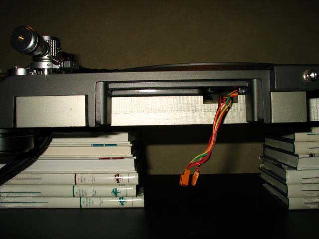
L-07D raised up on a stack of hardcover textbooks positioned under the deck's handles shown above. Positioning the books in this way allows access to the motor attachment bolts and wiring.
7. Remove black plastic cover behind motor on undersurface of deck, held to deck with four small black screws. Feel up inside the opening exposed by removing the black plastic cover. Feel for the wires. If any wire ties are present up in there, they will need to be removed carefully without damaging the wires. A choice may be made to turn the deck upside down on pillows (Important: Be sure to remove cartridge/headshell combo, tonearm, tonearm cable and tonearm base first!) to see clearly. Be extremely careful not to damage any wires. After carefully removing wire ties from that space, turn the deck upright and back on elevating safe supports. Tip: Do not replace any wire ties in this area during re-assembly.
8. Remove two screws holding rear connector cover to back of turntable. The connector cover is the part with the serial number label. The connector cover contains the rear connector PCB and rear connector socket. Slide the rear connector cover downwards and out of its channel. Tip: Of the screws that hold the underside black plastic cover (black plastic plate with four screw holes) in place and the rear connector panel in place, all six are small black screws. If looked at closely one will see that the two screws that secure the rear connector plate are slightly shorter than the four screws that secure the black plastic cover.
9. Cut away any wire ties around wires going to the rear connector PCB. Be extremely careful not to damage any wires.
10. Locate the two wire looms that originate from the motor at their connection with the rear connector PCB. The two looms that originate from the motor are the ones that terminate in four-pin and ten-pin female connectors that mate to corresponding male connectors on the rear connector PCB. Disconnect the four-pin and ten-pin female connectors from the rear connector PCB. Optional: Disconnect remaining wire connectors from rear connector PCB, so that rear connector assembly can be set aside instead of left hanging from back of turntable.
11. Feed the wire looms that originate from the motor (and two connectors on the ends of the wires) back through the channel between the wood and ARCB bases, toward the motor and downwards and out though the access hole exposed in Step 7 above.
12. Loosen the hex grub screw that supports the motor thrust bushing about one turn. This screw is located on the bottom of the turntable in the center of the aluminum motor support frame portion of the ARCB plinth.
13. Remove all six motor bolts (also located on the bottom of the turntable in the aluminum motor support frame portion of the ARCB plinth) and separate the motor from the plinth. I like to lay the screws upright on a flat surface in the same relative position they were in before removal so I can return each screw to the same motor screw hole.
14. Carefully lift the motor upwards. Feed the wire looms and rear connectors upwards and out though the opening in the rear of the motor receptacle of the ARCB plinth. Now the motor and its wiring are free from the turntable.
15. Take motor to the workbench. I like to use an appropriately sized roll of tape to lay the motor in to support it. This will keep the thrust bushing support screws from contacting the workbench. The diameter of the roll of tape should be the right size to support the motor base without blocking the wire channel. Wear thin rubber gloves when working inside the motor to keep skin oils from contacting motor parts.
16. On the top of the motor, remove the three hex screws and washers holding the platter attaching plate to the spindle. Lift the plate off the spindle. Lifting will be against the pull of a magnet. IMPORTANT: If platter attaching plate will not slide up the spindle, do not force anything and do not attempt to grasp the spindle with a tool. After completing the instructions in this paragraph after this sentence, complete step 17, skip step 18 and proceed to the second sentence in step 19 to complete the service without removing the platter attaching plate from the spindle. Remove the small cardboard wire cover plate from bottom of motor held in place by small single screw. Some motors have a ground wire attachment point between the screw head and the small cardboard wire cover plate. IMPORTANT: Don’t loosen or remove the three screws that hold the Thrust bushing cover on! Doing so would break the bearing house's oil seal.
17. Note orientation of motor top cover. Remove five black Phillips motor cover screws from the top of the motor and lift off motor top cover.
18. Now see a round plate with two (three in the L-07DII) eccentrically located screws on top of the stator PCB. Don’t remove or loosen those two screws! Use a thin flat blade screwdriver to gently pry the plate up off of the stator PCB. Apply the screw driver to the inner edge of the plate at a location on the PCB between stator windings. This is done by prying very gently against a magnetic force. Be very careful not to damage the stator PCB during this step. Remove plate and set aside, maintaining upright alignment so plate will subsequently be reinstalled with same side up.
19. With the platter attaching plate and round plate removed, there is no magnetic force holding the remaining motor parts together. Gently pull the spindle upwards, out of the bearing well, and and out of the motor. IMPORTANT: The ball bearing usually falls out when the spindle is pulled up from the bearing well. I recommend doing this operation over a towel-lined plastic bin. I use a plastic 16 quartz storage bin which measures 16”length x 11”width x 6”height with a towel lining the bottom. This way, when the ball bearing falls out it will hit the soft towel and it will be captured in the bin. This method prevents the ball bearing from following a possible tendency to bounce off the work surface and down to the floor!
IMPORTANT: Do not remove or loosen the three screws that hold the magnetic rotor to the spindle! Doing so would cause the rotor magnet to become un-centered.
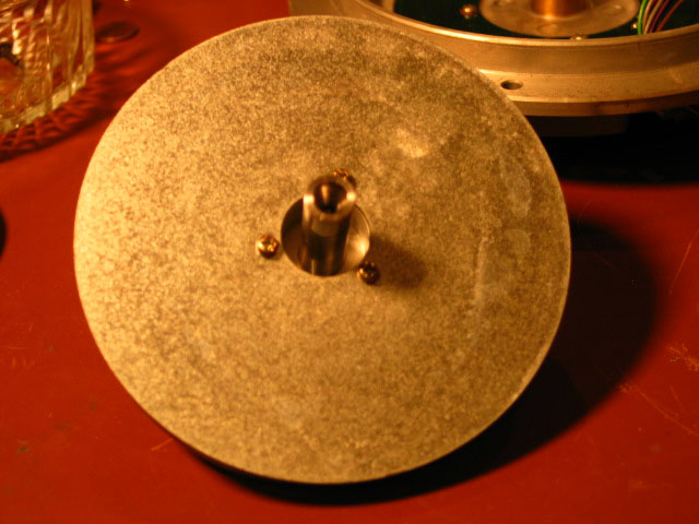
The photo above shows how a tape roll can be used to position a motor for portions of a servicing.

The photo above shows the motor on a two-inch wide by four and one half-inch diameter tape roll. The roll supports the motor base without blocking access to the rear wire passage area.
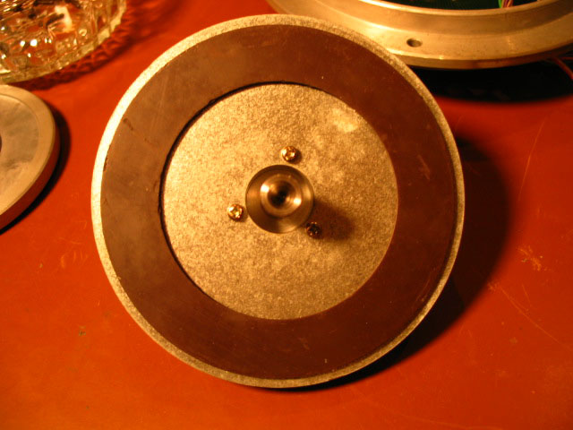
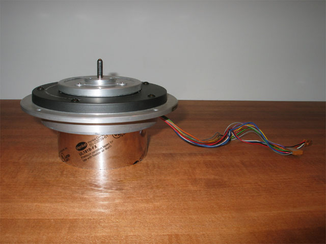
A properly disassembled L-07D motor is shown above.
Caution: Do not loosen these three screws, or the rotor magnet will become un-centered!
If the rotor becomes un-centered, a special custom made centering jig is required to re-center it.
The jig is applied and the three screws are tightened with the jig holding the rotor centered to the bearing shaft.
20. Five brass washer shims will fall out or into the bottom of the motor casing, if they were present. The brass washer shims were spacers located between the Stator PCB (coil side) and the motor casing. The five motor cover black screws passed through them. The washer shims are used to provide additional clearance between the stator coils and the top surface of the rotor. Only about half the motors I have worked on had these five brass washer shims. Set washer shims aside (if they were present).
21. Test resistances of coils and Hall elements on stator PCB, if motor had a fault before servicing. Open circuit between any two pins on a Hall element means the Hall element is bad. If deck quartz locked properly before servicing, Hall elements and coils are good. If any stator windings are bare, cover with a few coats of clear lacquer paint and let dry completely before re-assembly.
22. Clean any dirt, debris, wear particles and old lubricant from the bearing well, Teflon thrust bushing, ball bearing, and bearing shaft using isopropyl alcohol and cotton swabs. Let dry completely. Be sure no lint from cleaning is left behind.
23. Lightly oil the ball bearing socket on the end of the spindle bearing, and the shaft of the spindle bearing. Lightly oil the inner walls of the bearing well bushing. Now add exactly 0.30 cc of oil to the bearing well, which will cover the Teflon thrust bushing. (Use an Insulin syringe for oil measurement and delivery.) I am currently using Red Line pure synthetic 20-weight racing motor oil and I am extremely pleased with it in this application.
24. Insert the ball bearing in to its receptacle at the end of the spindle shaft. The oil will hold it in place.
25. Insert the spindle bearing shaft with ball bearing at the end into the bearing well of the motor casing. The oil will cause a seal. It will take a while for the magnet to go all the way down as air is gradually expelled BY GRAVITY ONLY - Do not apply a downward force to "help" seat the bearing. If the ball bearing drops into the well before inserting the spindle bearing shaft, the edge of the ball receptacle may get hung on the ball if the ball ends up off-center against the bushing inner wall. The ball should remain in the receptacle at the end of the spindle shaft during re-assembly and seating. Do not force the rotor down! Doing so may expel oil. Do not spin the rotor while it is seating! Doing so will just spread oil and block any air escape passage(s) that pressure resulting from gravity has established.
26. Once it is confirmed that the bearing has fully seated, it is time to start re-assembly. (The rotor will now spin very freely with its new lubrication.)
27. Place the five brass washer shims (if originally present), one on each of the screw holes, on the top the five female screw holes in the motor casing. Tip: Use cotton swab sticks to keep the brass shim washers from falling out of place during re-aasembly.
![]()
The photo above shows the brass washer shims that are present in some motors.
![]()
The photo above shows the proper location of the washer shims (red arrows). They are shown being held in place by cotton swab sticks. Replacing the stator over the sticks keeps the washer shims from falling to the base of the motor during re-assembly.
28. With stator coils face down, feed stator wiring through wire passage in motor casing. Replace the stator. Align stator screw holes with motor base screw holes. Align stator so that wiring is in line with wire passage in motor casing. Take up all slack in the wiring so that no wires touch the rotor once assembled. If washer shims are present and held in place by cotton swab sticks, lower stator so that each one of the five stator screw hole passages go over the corresponding cotton swab stick. Do not remove the cotton swab sticks yet, or washer shims may fall out of place.
A stator positioner is shown above. There are five per motor. The threaded portion of a motor top cover screw will occupy the space in the metal sleeve of the positioner.
Side view of the stator positioner shown above. They must all go on the stator in the correct orientation.
The correct orientation of a stator positioner is shown above. The thicker side is towards the motor coils. All five stator positioners must be oriented this way.
29. Reinstall the flat round plate. Note orientation of the two inner eccentric holes, which must line up with the two screws visible on the top (bare) side of the stator PCB. There will be a big pull on the round plate as it nears the motor, so be prepared. Carefully bring the plate down towards the stator. If washer shims are present and held in place by cotton swab sticks, lower round plate so that each one of the five round plate screw hole passages go over the corresponding cotton swab stick. If washer shims are not present, and cotton swab sticks were not used, align the plate so that each black screw will pass through one of the corresponding holes in the stator PCB and into the treads in the motor casing screw hole. Confirm proper alignment of all parts with screw holes. Make any minor rotational adjustments now.
30. Install motor top cover in proper orientation and inset five screws. Tighten only a bit while fully depressing the rotor.
31. Install platter attaching plate with three hex screws and lock washers. Sequentially cross-tighten all five black screws to final tightness while fully depressing the platter attaching plate. (These screws should never be very tight.) Re-install small cardboard wire cover plate from bottom of motor held in place by small single screw. If a ground wire attachment was held in place by the screw, reinstall now. Just get screw threads started but do not tighten or compress small cardboard wire cover plate yet.
32. Most important: There is not much clearance between the side of the rotor and the wiring inside the motor. Once everything is reassembled, gently pull at each individual wire coming out of the motor to remove any internal slack, and maximize clearance with the magnet. Failing to do so could result in contact of the rotor with one or more wires, leading to abrasion and possible failure. Do this with the wire cover plate somewhat loose as per 31 above. Lightly compress the small cardboard wire cover plate against the wires and tighten the wire cover plate retaining screw once all internal slack has been taken out of all the wires.
33. The next job is to get motor back into the turntable with the motor upright. Do not turn motor upside down once lubricated, or some oil may be lost.
34. Reinstall motor back into turntable. If the round metal motor support plate was previously removed, be sure to re-install it before replacing the motor back into the ARCB plinth. Feed all wiring back through channels. Be sure to take all slack out of motor wire looms while lowering and seating motor.
35. Reinstall and sequentially cross-tighten six motor retention hex head bolts from below. Tighten snugly. Don’t over-tighten. These are threaded into aluminum.
36. Tighten the small hex grub screw that supports the thrust bearing cover until it touches the bearing cover, not overly tight but just right as it is used as support to prevent the motor cover from deforming from the weight of the platter. In other words, tighten the center support screw until resistance is felt and then just a tiny bit more to take any slack out of the threads. This should be "slightly snug", but not tight. Don't tighten it to the point of deforming the bearing thrust plate cover.
37. Re-install flat black plastic plate behind motor with four screws
38. Reconnect the two motor wire connectors to the rear connector PCB. If the other connectors were disconnected from the rear connector PCB earlier, reconnect them now.
39. Replace wire ties on wiring coming out of back of turntable to rear connector PCB. I use two ties. Don’t over-tighten. Leave a little slack to make removal of the wire ties easy in the future. To make the next go around easier, don’t put any wire ties around the wires at the level of the black plastic cover. Those would be very hard to remove without turning the deck upside down.
40. Re-install rear connector assembly by sliding it upwards in its channel, being careful to safely route/manage the surrounding wiring. When sliding the rear connector assembly plate up into its channel, the wires will probably try and get pinched between the plate and the bottom rear of the gray wood plinth. Use a fingertip to push the wires up out of harm's way while pushing the rear connector up the channel into final position. While holding the rear connector assembly fully upwards (to protect any wiring from slipping between the rear connector assembly and the plinth), insert and tighten the two screws that secure the rear connector cover.
41. Lower the turntable on to its stand. When letting the unit down "from the lift," get it down to the height so that there is the minimum number of books where the footers are still elevated from the turntable stand. Next rotate the table into its final resting position using the books. Go slow so that the books don't jump out. Once the deck is in final position, and only one book is on each side, remove the book on the left (operation and speed switch side) first. When lifting the deck by the right handle to remove the final book, be careful that the tonearm cable does not become pinched under the right rear footer when letting it down, if tonearm was left in place for servicing. Reinstall subplatter with three screws and replace platter sheet.
42. Connect Control Unit cable to socket on rear connector.
43. Connect ground wires. Ground the rear ground point of the Control Unit to the ground point of the phono stage. After reinstalling the tonearm base, tonearm and tonearm cable if previously removed, (see Step 45 below.) also ground the tonearm cable ground wire to the ground point of the phono stage. The left side of the deck may need to be raised briefly to feed the tonearm wiring through the tonearm base. Hence there should only be one wire connected to the ground point knob-screw on the back of the Control Unit.
44. Connect Control Unit mains power and test set.
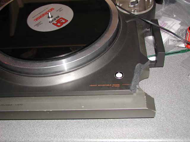
45. Once satisfactory operation is confirmed, re-install tonearm base, tonearm cable and tonearm if previously removed. The left side of the deck may need to be raised briefly to feed the tonearm wiring through the tonearm base. Set tonearm height based upon notations made in Step 3 above. Level the platter with a circular bubble level by using the subplatter top surface as the reference surface for platter leveling. The platter sheet has a slight crown and should not be used for leveling. The bubble level in the plinth is not usually perfectly parallel to the platter. When leveling the deck, start with the footers at the lowest height. Raise only the minimum amount needed to get the deck level. Once level, go around to each footer and give the footer adjustment knob a feel for being snug. All four should be snug. If any are loose, the deck will wobble. At least one of the footers should be all the way at lowest height when done.
46. Check and/or adjust cartridge alignment and anti-skate.
47. Enjoy the L-07D with a freshly lubricated motor bearing!
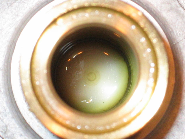
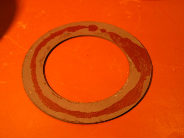
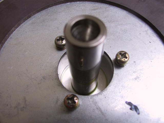
The above bearing was opened for inspection three years after being lubricated with Red Line pure synthetic 20-weight racing motor oil. The thrust bushing remains covered with clean clear oil.
This method is only a guide line. The author is not responsible for any damage that may be done to any part of the turntable, persons or anything else resulting from any servicing.
Servicing the Tonearm Cueing Mechanism
The cueing mechanism can develop faulty operation resulting in it dropping too quickly or too slowly. The cueing mechanism has a rotating cam at the bottom of a cylinder that pushes a piston upwards. A small amount of a highly viscous silicone fluid also sits in the cylinder, and the motion of the piston pushes the silicone with it, coating the cylinder walls. When the cueing lever is brought to the resting position, the cam rotates and stops forcing the piston upward. Gravity brings the piston back down with the assistance of a coil spring, but the silicone in the cylinder slows its motion. When correctly set up, the stylus should drop slowly enough that no objectionable thump is heard through the speakers when the stylus contacts the record. It should take 4 seconds for the stylus to drop to the record from the time the cueing lever is lowered.
If the cueing mechanism is either sticky or insufficiently damped, the cueing mechanism should be serviced.
Author's Method for Servicing the L-07D Tonearm Cueing Mechanism
*** Read this a few times before considering doing the servicing. ***
1. Remove headshell and cartridge. Be careful to protect these items from any damage.
2. Remove tonearm. Note how close the lifter support screw is to the rubber bumper with the cueing mechanism fully up.
3. Remove screw securing lifter support to cueing mechanism. Remove lifter support.
4. Loosen the Allen grub screw(s) securing the cueing mechanism to tonearm collar with a 1.5mm metric Allen key. Some L-07D tonearms have one screw securing the cueing mechanism to tonearm and others have two screws. This was a manufacturing variation.
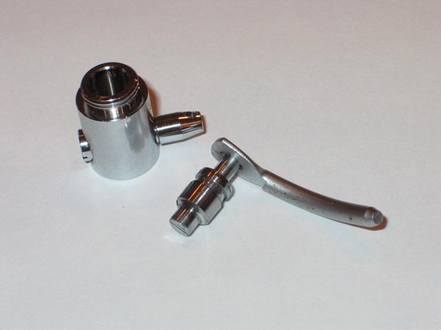
5. Remove cueing mechanism from tonearm collar
6. Unscrew cover from top of cueing mechanism. Remove inner spring.
7. Remove piston. If piston is sticking, reattach lifter support and then use the lifter support to pull the piston out of the cylinder.
8. Clean all old silicone from cylinder and piston using isopropyl alcohol and cotton swabs. Let dry completely. Be sure no lint from cleaning is left behind.
9. Apply 300,000 cSt (centiStoke) silicone to recessed groove near the top of the piston. Apply 340 degrees around. Leave 20 degrees without silicone so that air can escape as the piston descends during operation. Apply the lightest possible coating of silicone to the upper third of the inner wall of the cylinder all around. Apply the lightest possible coating of silicone to the bottom surface of the piston that will contact the cam at the base of the cylinder. Do not place any silicone in the cylinder below the upper third of the cylinder.
10. Reinstall the piston. After a few up-down cycles, air should be expelled, and the piston should drop at a smooth controlled rate. Wipe off all excess silicone from the external surfaces.
11. Reinstall spring and cover.
12. Reinstall cueing mechanism into tonearm collar. Reinstall lifter support and screw. Adjust height and rotation of cylinder such that rubber bumper follows above lifter support during horizontal tonearm movement, and clearance between the lifter support screw and the rubber bumper with the cueing mechanism fully up is identical to that before servicing.
13. Tighten Allen grub screw(s) securing the cueing mechanism to tonearm collar with a 1.5mm metric Allen key.
14. When working correctly, the mechanism will drop fully in 6 seconds with the tonearm parked in the tonearm rest, and in 4 seconds to the record with the tonearm being lowered by the cueing mechanism.
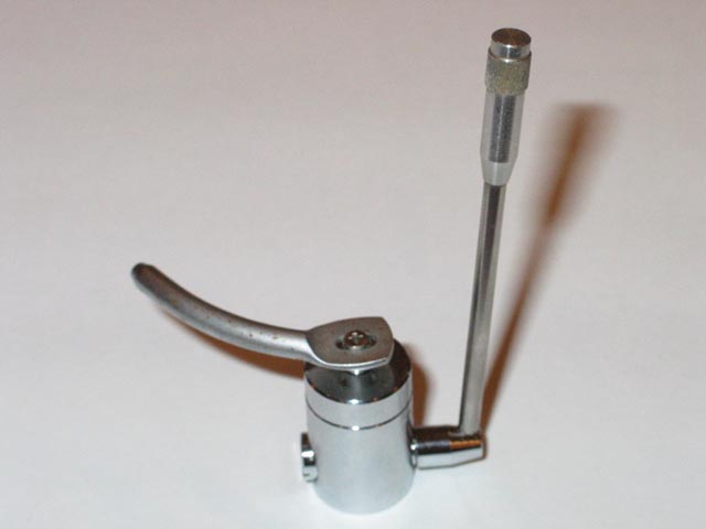
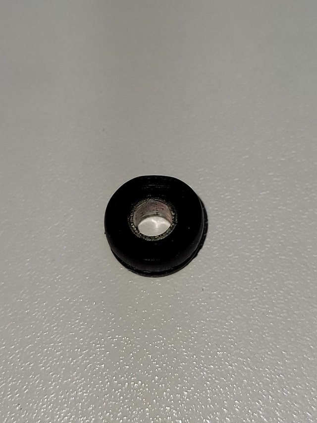
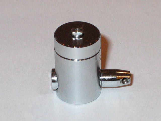
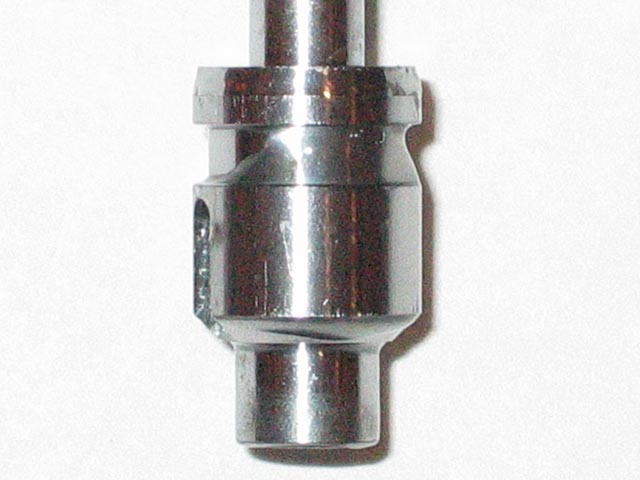
The L-07D tonearm cueing mechanism is shown above. (The Phillips screw shown is not the original. This cueing mechanism is from my used spare parts collection.)
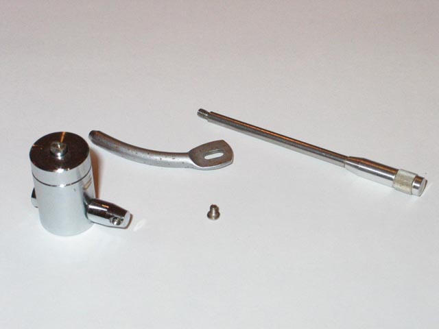
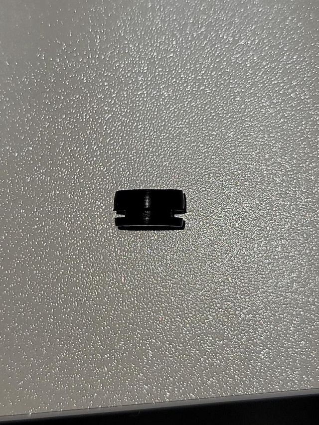
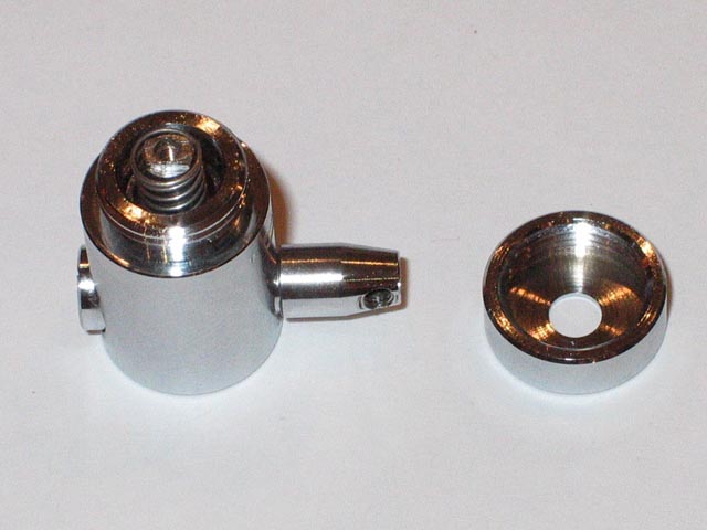
Disassembly in progress shown above.
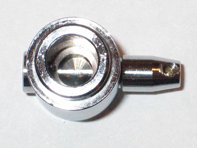
Cueing mechanism cylinder ready to be opened for servicing shown above.
Top cover removed exposing inner spring. The spring assists the mechanism in dropping the tonearm against the resistance of the silicone damped piston in cylinder.
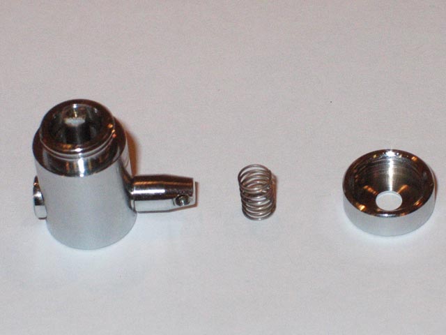
Removed spring is shown above.
Reattached lifter support used to pull piston out of the cylinder shown above.
Hardly any silicone left after 20+ years resulted in this cueing mechanism dropping too quickly.
Cleaned cylinder bore shown above. The cam is seen at the base of the cylinder.

Replacement silicone from www.turntablebasics.com. I tried both the 100,000 cSt and the 300,000 cSt varieties. The 100,000 cSt silicone was too thin and the piston dropped too quickly. The 300,00 cSt silicone is the correct thickness for the L-07D cueing mechanism.
This method is only a guide line. The author is not responsible for any damage that may be done to any part of the turntable, persons or anything else resulting from any servicing.
In the Literature section of this web site, I have posted a number of documents that I have authored. I find these to be helpful references in planning and executing repairs. I am happy to help any fellow L-07D owners with repairs on their sets. I can provide needed information and/or perform the repairs myself.
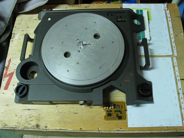
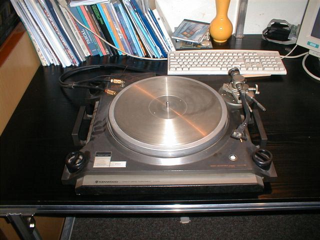
Seen above is a scrap set that I use for repairs. As I can mount a motor for testing in this scrap set, an owner can just ship the electronics and motor to me, and not have to send the entire turntable (which would be very heavy and therefore costly to ship). As cracked plinths can result from shipping mishaps, this also lessens the risk and worry regarding shipping damage when I do repairs. I also like to use this scrap set for Control Unit testing and adjustments, before connecting to an audio-system-connected L-07D for wow and flutter adjustments, which requires a pickup.
Repair Services
****You are welcome to contact me by e-mail at KenwoodL07D@aol.com if your L-07D is in need of servicing or repairs :
I absolutely will not accept an entire deck for servicing unless hand-delivered by the owner. Otherwise and usually, the owner ships me the Control Unit, Motor and Rear Connector Assembly for diagnostics and generally for the following services, which may vary according to requirement(s):
Replace 35 or 36 (depends on generation of logic board) capacitors in the Control Unit with upgraded parts.
Replace all 4 rectifiers in the Control Unit power supply with upgraded parts.
Replace power supply power-transistors with upgraded parts if necessary.
Meticulously clean the Control Unit inside and out.
Repair any electronic faults, including replacement of any defective IC's. (IC replacements and IC sockets at additional parts and labor costs.)
Replace all electrolytic capacitors on the rear connector PCB with upgraded parts.
Service motor, including disassemble, replace Hall element(s) if defective, true rotor if needed, clean and lubricate bearing with long-life pure synthetic oil. (Hall element replacement at additional parts and labor costs.)
Test unit, oscilloscope and VOM adjust Control Unit.
Modulation Domain Analyzer adjust Control Unit.
Any restoration and/or repairs additional to the above at additional parts and labor cost as required.
Customer pays all shipping-related costs both-ways. (Which means return shipping is an additional fee.)
I will not be responsible for any shipping damages.
Shipping Damage
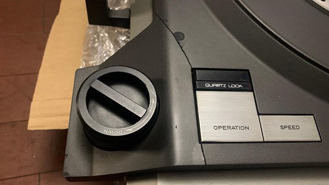
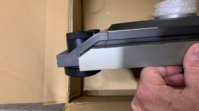
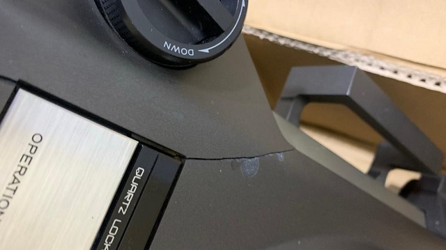
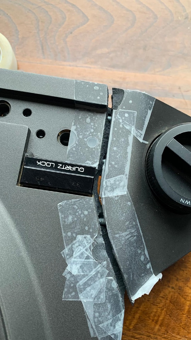
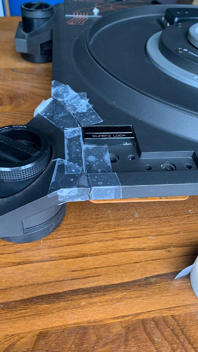
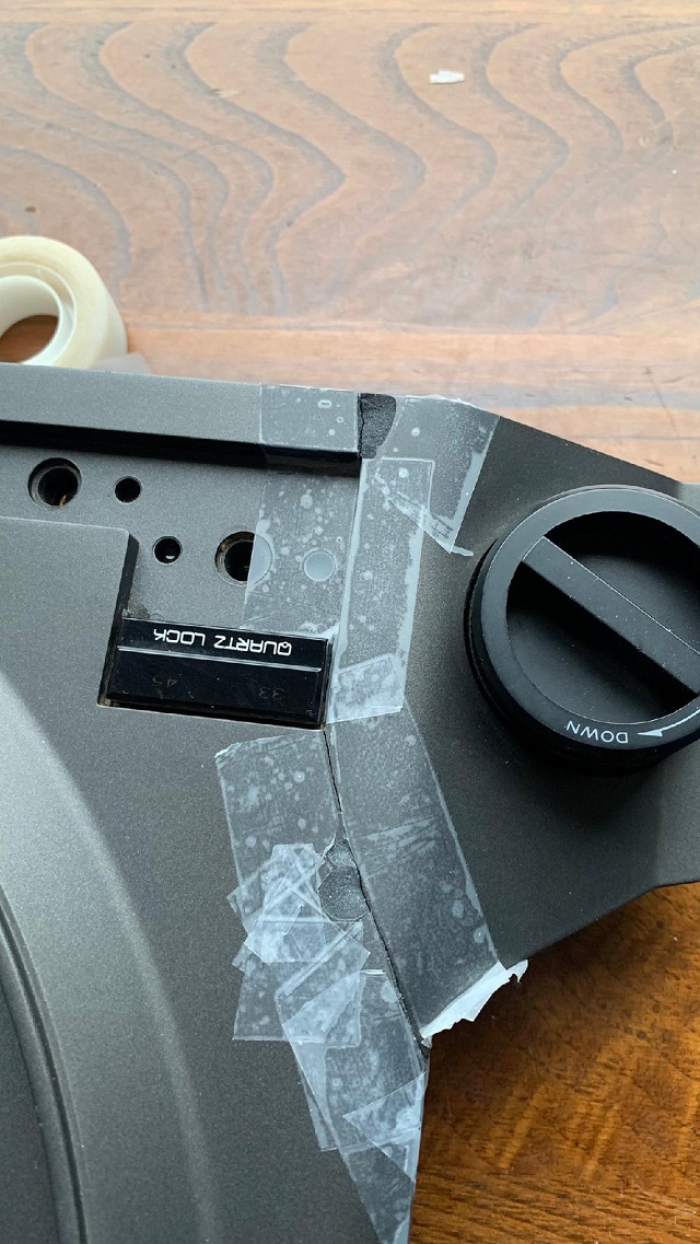
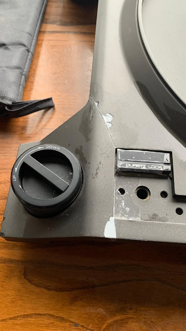
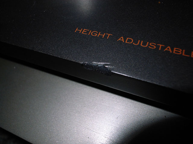
Great care should be exercised in shipping the L-07D. The heavy mass of the deck and the hard but brittle concrete resin structure of the ARCB plinth put the deck at risk for plinth fractures during shipping. Some unfortunate results of improper shipping preparations are shown below:
The corners are the most vulnerable areas for shipping damage to occur.
Don't let any tape touch the deck! It can pull off the finish when removed.
Shipped in a dresser drawer!
More bad preparations for shipping!
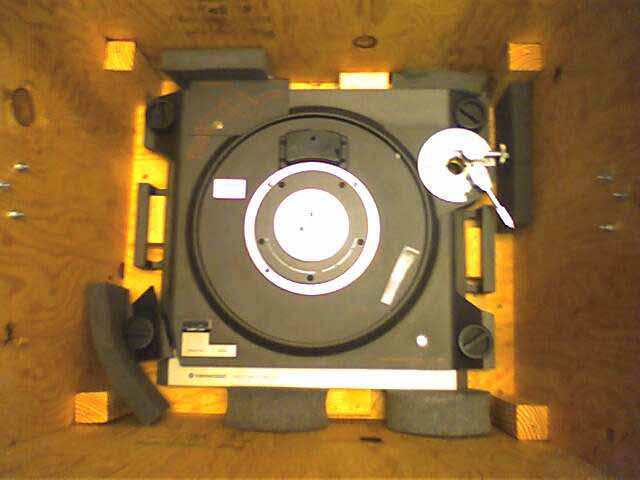
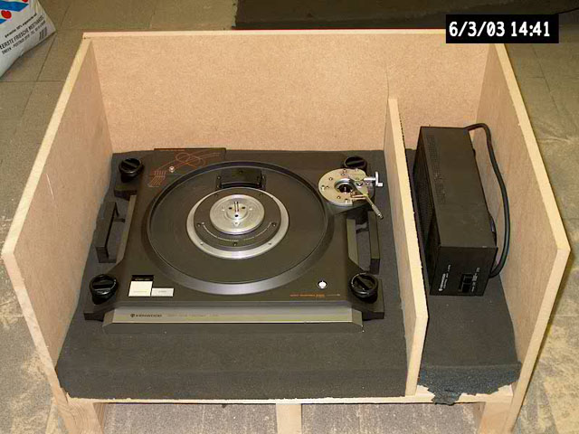
A custom crate was used, but no padding on the bottom!
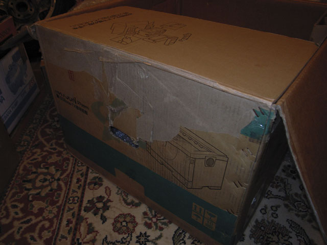
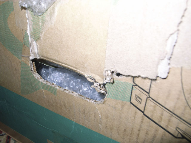
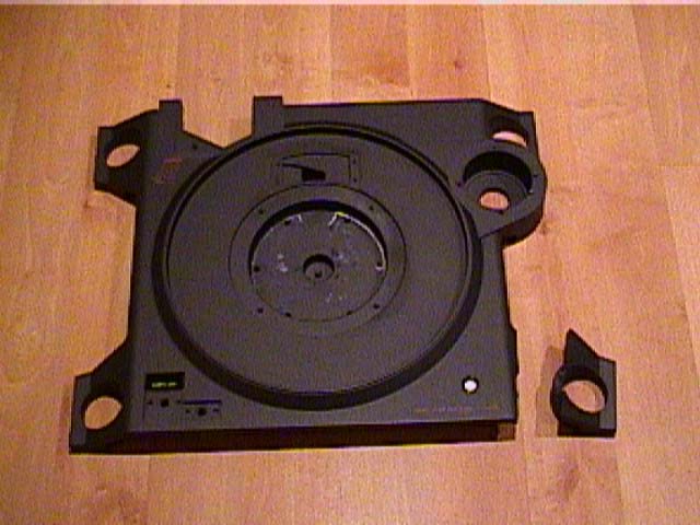
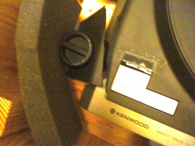
The pics above show a deck that was shipped in a cardboard box.
Shipping the L-07D
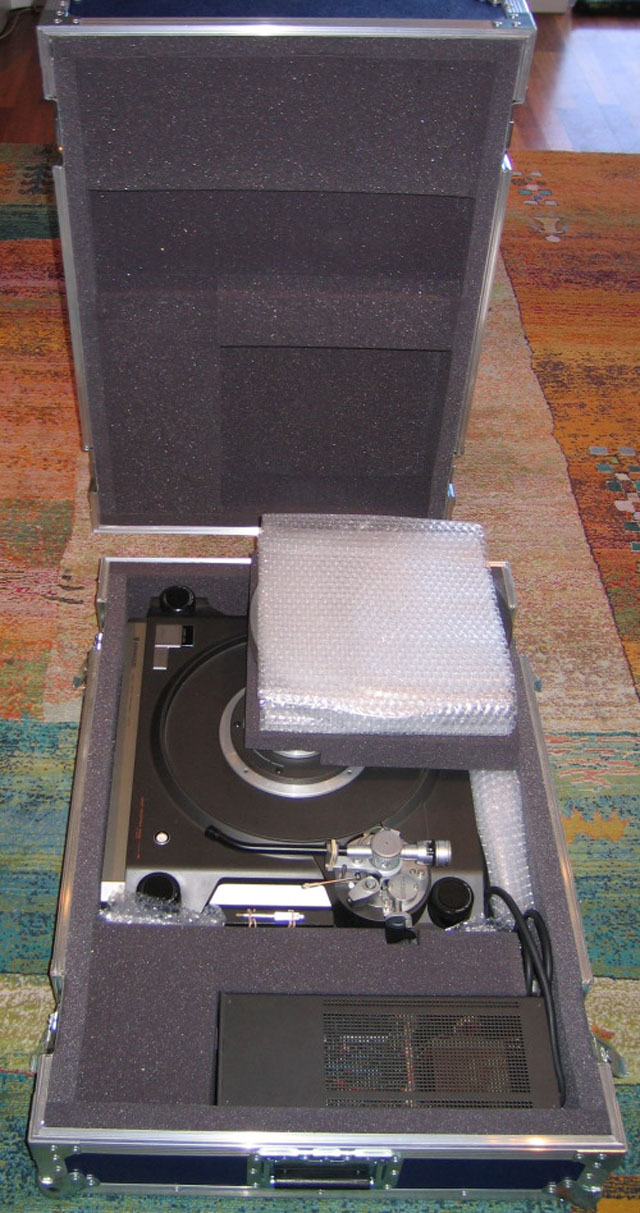
A flight case that has been customized for shipping the L-07D appears to be a reasonably safe container to ship the L-07D in. An example is shown below:
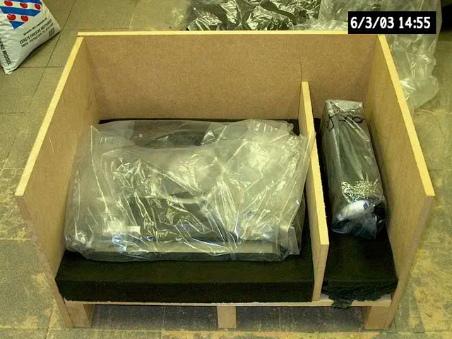
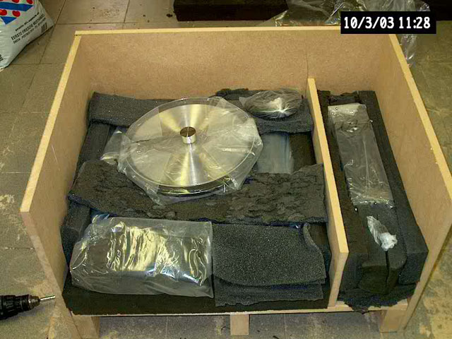
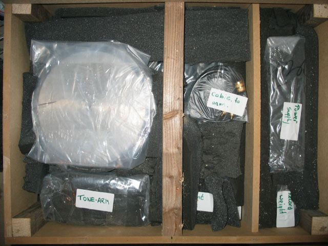
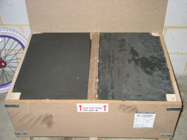
Anorther method would be to use a custom reinforced crate made from MDF with a pallet bottom, wrapping all sections in plastic and cocooning the deck with heavy foam. See pictures below:
This method is only a guide line. The author is not responsible for any damage that may be done to any part of the turntable, persons or anything else resulting from any crate work, packaging, and/or shipping.
All trademarks and rights belong to the OEM and are reproduced here for information purposes only. Copyright © 2003-2022. All rights reserved.