![]()
![]()
![]()
![]()
![]()
![]()
![]()
![]()
![]()
![]()
![]()
![]()
![]()
![]()
![]()
![]()
![]()
![]()
![]()
![]()
![]()
![]()
![]()
![]()
![]()
![]()
![]()
![]()
![]()
![]()
The Tonearm Base and Tonearm
The tonearm base is a massive 3 kg structure that contains a Vernier-type geared mechanism to adjust Vertical Tracking Angle (VTA.) A four jaw Collet chuck, similar to the type used on drills, rigidly secures the tonearm to the tonearm base. The chuck is opened to adjust VTA and locked once VTA is adjusted. VTA can be adjusted "on-the-fly", while listening to the record. A calibrated rod and arrow mechanism is used as a reference to record VTA setting. This is a useful feature when using multiple cartridge/headshell combinations. The E.I.A. standard headshell collar allows use of any removable headshell with the L-07D tonearm. The tonearm itself uses resonance-canceling composite design. The tonearm tube is made from aluminum covered with layers of carbon and boron. Tonearm bearings are oversize hardened roller bearings with no play. The headshell is made from seven layers of carbon and boron. Litz wiring is used in the tonearm and headshell. The tonearm cable is massive and has a screw on collar that secures the DIN connector to the tonearm. RCA male ends are heavily gold plated. The anti-skate mechanism uses a weight and string mechanism with no springs to wear out. Tonearm cueing is hydraulically damped. The tonearm itself is not damped. Tonearm effective mass is rather high at 17g. and will therefore be better suited to medium (between 10-µ/mN and 20-µ/mN) and low (less than 10-µ/mN) compliance cartridges.
The L-07D instruction manual states:
Carefully selected inner wires transmitting electrical signals faithfully
Pure copper Litz wire is used throughout the electrical transmission system. Our unique penta-structure and two core shielded cable gives optimum performance. In the output cord + and - signal lines are arranged symmetrically and they are completely shielded. Each conductor is a Litz wire consisting of 168 wires of 80 udia, thus DC resistance is reduced to the limit. For the inner cord in the tonearm, a penta Litz wire each conductor of which consists of 56 wires of 50 u dia.is used. For the head shell wires, silk-covered Litz wires of 12 milli-ohm are used.
The L-07D brochure states:
Signal transmission lines using new Litz wire
Kenwood engineers have employed an improved Litz type wire that maintains the high quality of the reproduced signal at the input of the phono preamplifier. The new, silk-wound wire uses a flat penta-structure (patented) that locates the wire in the precise center of the tonearm pipe for minimal capacitance. Its nearly 100% pure copper strands are twisted to provide ultra-low DC resistance. In addition, the output cord is a shielded two-core design for improved cross-talk, signal-to-noise and dynamic-range characteristics. Even the locking-type tonearm connector pins have not escaped attention; they are heavily gold-plated in a design that gives five times greater contact area than conventional types.
Highly rigid, tapered tonearm with 3-layer laminated construction in low-resonance design
When normal variations in recorded signal levels are in the order of only a few microns, even the slightest instability in the tonearm can result in distortion. Actually, in conventional tonearm design, large amplitudes at resonant frequencies can result not only in horizontal and vertical movement, but even in twisting and "rattling" of the pivot. The Kenwood tonearm, designed as a highly rigid link in the L-07D system, achieves a remarkable freedom from such resonance problems. One feature is its pipe, a unique three-layer laminated structure using highly rigid materials: hard aluminum, boron fiber and carbon fiber. Each material is selected for its ability to restrict resonance amplitudes as well as for its low mass and relatively large elastic modulus. At the pipe/holder junction, where the influence of vibration is many times greater, a tapered six-layer structure is used. This careful design is largely responsible for the accuracy and clarity of reproduction across the audible range, particularly at the low level frequencies that are most difficult to reproduce authentically.
The carbon-boron headshell
Headshell resonance usually occurs at frequencies at which the ear is most sensitive- between 1KHz and 5 KHz - and is the reason that headshells often have a distinct tonal quality. To avoid this problem for the L-07D system, Kenwood engineers designed a headshell that raises resonance out of the critical audible range, while fulfilling basic requirements such as rigidity and low mass. The new design uses carbon and fibers laminated in opposed fiber directions to increase torsional strength.
Improved anti-skating device
A new static-balance type mechanism uses the anti-skate weight on a pulley for precise adjustment.
Your choice of cartridge
To allow you to choose the ideal cartridge for your needs, the L-07D tonearm is designed with a sub-weight for use with any cartridge and headshell with a combined maximum weight of 34 grams, to a minimum of 10 grams.
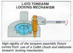
Tonearm base with precision Collet chuck provides extreme rigidity and stability
Too many tonearms are treated as add-on features without regard to the probable effects of vibration caused by imperfect fixture to the base. Kenwood engineers take a different view. This is why you will find an extra-wide diameter, stainless steel tonearm shaft, and a massive base clamped directly to the metal frame that links the tonearm to the fixture. A genuine Collet chuck is is used - the same type employed for precision machinery - which reaches a pressure force of 166.8 x 10³. Also contributing to greater stability is the unique use of extra-large precision bearings. The total 3 Kg weight of the arm base, plus its mass concentration, and ultra-rigid linkage with the turntable base metal-insert frame, presents a united front to all potential tonearm-generated resonance and partial resonance.
Precision helicoid arm height adjustor
The helicoid type of arm adjustor is the same as that used in precision instrumentation. It allows precise adjustment to be made in 1mm steps.
Using the L-07D with other tonearms
To ensure total flexibility in the sound reproduction system, the L-07D is designed with a sub-base as an option extra. Although the J-shape arm is standard for the L-07D, an optional straight-arm semi-integrated type tonearm is also available.
Cartridge Alignment
L-07D Cartridge Alignment Measurements
Critical measurements for the L-07D tonearm are:
Spindle-to-Pivot distance: 229.5mm
Tonearm Effective Length (Leff): 245.0mm
Spindle Diameter: 0.2825 inches
Calculated Overhang (Baerwald): 16.8mm
Calculated Overhang (Löfgren): 17.2mm
My opinion is that Baerwald alignment (of 16.8mm overhang) sounds better than Löfgren alignment. Baerwald alignment geometrically allows better tracking on the inner grooves. The non-damped ultra-rigid design of the L-07D tonearm mechanism works better at the inner grooves when Baerwald alignment is used.
A Microsoft Excel spreadsheet showing calculation of Baerwald and Löfgren cartridge alignment calculations is posted at:
Kenwood L-07D Baerwald-Löfgren Cartridge Alignment Spreadsheet You can use the tabs at the bottom left of the spreadsheet to toggle between Baerwald and Löfgren spreadsheets.
Author's Recommended Method of Phonographic Cartridge Alignment on the L-07D
For geometry to be correct, overhang and zenith must be perfect at proper VTA. I have used a several alignment tools including a metal Denessen Soundtractor and a Turntable Basics Phono Cartridge Alignment Tool. I have also measured actual overhang beyond the spindle along the overhang line.
Now I only use a custom made for the L-07D Wally Tractor. The Wally Tractor is far superior to any other method and/or device that I have tried in terms of accuracy as it is custom made exactly to the L-07D's tonearm geometry. I have reached the opinion that setting cartridge alignment with any universal cartridge alignment tool will result in imperfect cartridge alignment. For instructions on phono cartridge alignment, the reader is referred to Wally's Complete Turntable Setup Procedure which can be found on Wally Malewicz' web site: Wally's Vinyl Corner. If you order a Wally Tractor, be sure to let Wally know that the spindle diameter is 0.2825 inches.
I use Wally's recommendation to set SRA at 92 degrees. First set VTA so that the headshell is parallel to the record surface at correct VTF and at correct overhang and zenith per alignment protractor. Theoretically SRA should now be at 90 degrees. Now raise the tonearm at the base by 8.59mm to increase SRA 2 degreess to 92 degrees. (1mm increase in SRA = 4.29mm increase in rear arm pivot height). Next, reset overhang and zenith with alignment protractor and reset VTF. I then set azimuth with a non magnetic level on the headshell with the stylus raised off of the LP. You can loosen the headshell collar and then slight play of the headshell allows azimuth adjustment. The slight play is gone after finger tightening the headshell collar.
For setting VTF, forget about balance beam scales. They are not very inaccurate. Use a good digital stylus pressure gauge. Measurement should be taken at record surface level. All alignment parameters will affect VTF, so readjust VTF after completing platter leveling and phono cartridge alignment.
When zenith is properly set, the cartridge will be rotated slightly clockwise from the long axis of the headshell (when the headshell and cartridge are viewed from above). Achieving the necessary degree of cartridge rotation to set zenith correctly is generally not a problem with the L-07D headshell if the cartridge uses full length screws and nuts for attachment. However if the cartridge has fixed threaded screw holes, the captured design of the L-07D headshell finger might not allow sufficient cartridge rotation to set zenith correctly. Therefore, with cartridges that have fixed threaded screw holes and if correct zenith can not be achieved with the original headshell, I recommend the Sumiko HS-12 headshell, which is highly adjustable. I also recommend the Sumiko HS-12 headshell as an excellent alternative to the original L-07D headshell. If you have a Sumiko Flux Buster cartridge demagnitizer, it is very handy to use to position the headshell for final tightening of cartridge attachment hardware, off the tonearm and away from the turntable.
If you are using a DS-20 Outer Disk Stabilizer, pay careful attention to the tonearm cueing mechanism. It is important to prevent the stylus tip from contacting the Outer Disk Stabilizer, particularly when the platter is spinning, to prevent damage to the stylus and/or cartridge cantilever. With VTA optimally adjusted, be sure that the when the tonearm cueing mechanism is raised that the stylus tip is at least a couple of millimeters above the outer portion of the DS-20 (when DS-20 is on a record). If there is not enough clearance (and if there is room to raise the tonearm cueing mechanism cylinder further), adjust the tonearm cueing mechanism height by loosening the Allen grub screw(s) securing the cueing mechanism cylinder to tonearm collar with a 1.5mm metric Allen key. Prior to performing this procedure, the headshell should be removed and the tonearm should be removed from the tonearm base and taken over to a clean work area for this procedure. Do not put any force on the lifter support as you change the cylinder position or you may damage the cueing mechanism internally. Raising the cueing mechanism cylinder in relation to the tonearm collar will provide additional clearance between the stylus and the DS-20 Outer Disk Stabilizer. Re-tighten the Allen grub screw(s) after completing the adjustment. Please note that this procedure can only be done if there was some clearance between the screw securing the lifter support to the cueing piston and the rubber button above it when the tonearm is parked. Do not attempt this procedure if no clearance exists between the screw securing the lifter support to the cueing piston and the rubber button above it when the tonearm is parked.
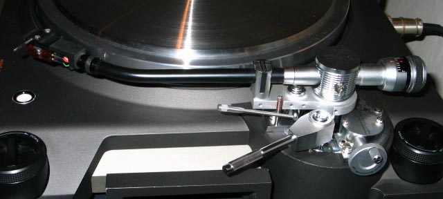
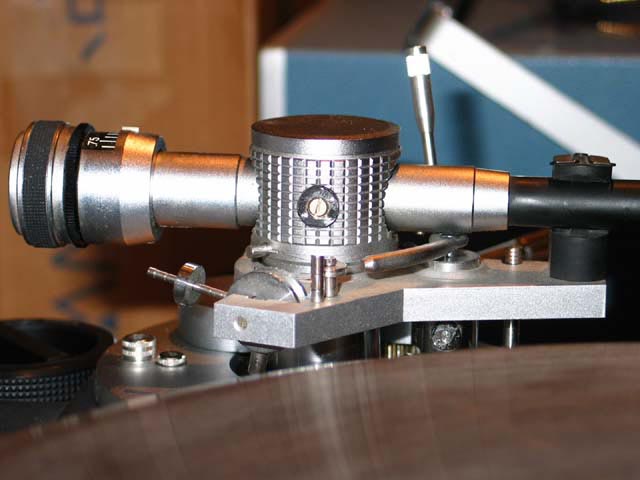
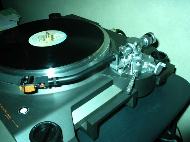
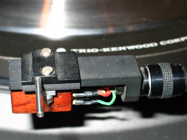
The L-07D tonearm, mounted on the turntable, is shown above.
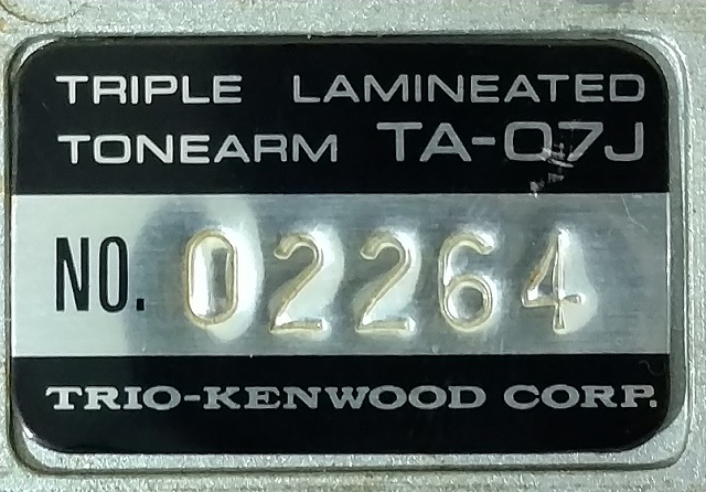
Tonearm tag located on the undersurface of tonearm platform is shown above.
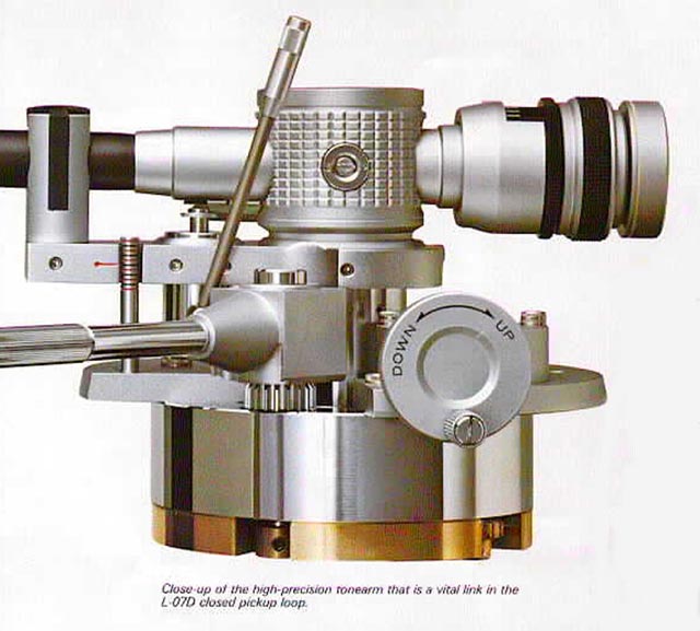
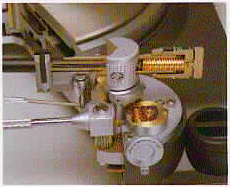
The massive VTA-adjustable tonearm base is shown in the illustration above. The tonearm base resides in a precisely machined well in the main plinth, and is rigidly bolted to the aluminum subframe of the plinth.
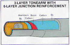
The image above demonstrates the composite construction of the tonearm tube. The inner pipe is Aluminum. Over the Aluminum, a second layer of Carbon fiber is laminated to the pipe. Over the Carbon layer, a third layer of Boron is laminated. The length of the tube is a three layer design. However, at the junction of the arm-tube with the pivot-counterweight assembly, the junction is reinforced with a total of six laminate layers. The design results in light weight, extreme rigidity, and excellent anti-resonance properties.
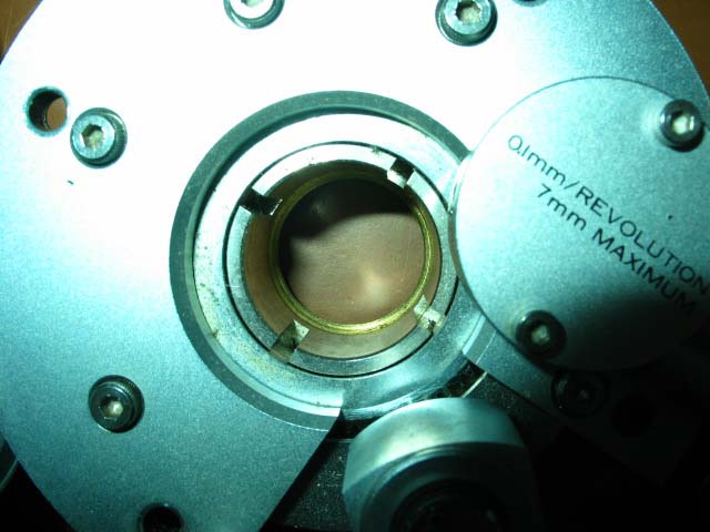
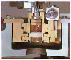
Collet chuck mechanism in the tonearm base shown above.
The tonearm base is mounted rigidly to the aluminum beam in the ARCB plinth with the four outer hex head bolts seen above.
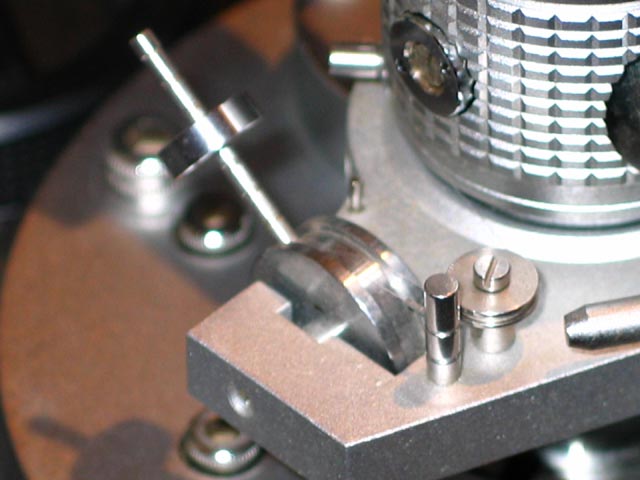
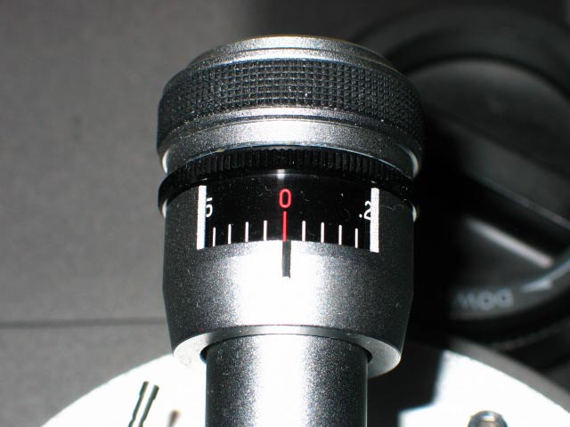
Details of the anti-skate mechanism are seen above. The pivoted weight acts via a thin Nylon thread to provide an anti-skate force to the tonearm. The weight is adjustable. It slides up/down on the calibrated pivoted support rod. Moving the weight up by one calibration will increase anti-skating force proportional to a 0.5 gram increase in Vertical Tracking Force (VTF). The weight is locked to the rod by a set-screw.
Anti-skate mechanism detail is shown. The cueing is hydraulically damped by silicone fluid.
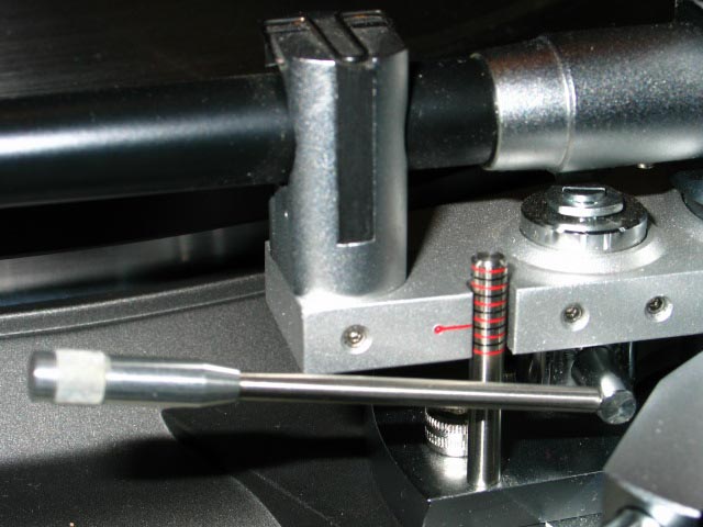
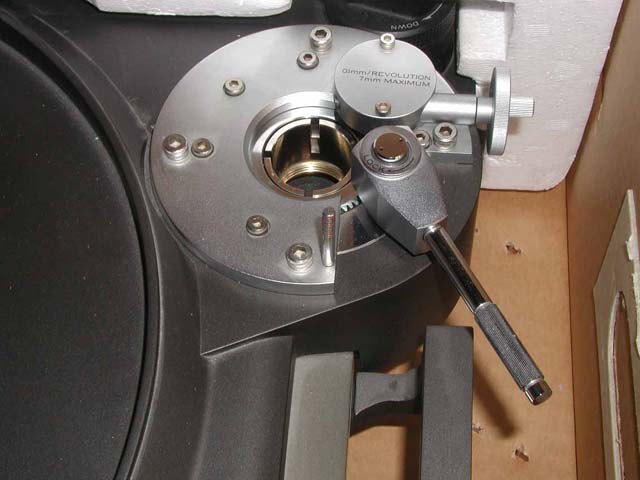
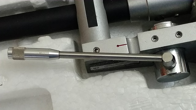
Tonearm elevation mechanism and VTA calibration rod is shown above.
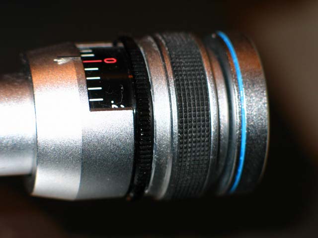
Details of the tonearm counterweight are shown above.
Large handle on the tonearm base in the picture above is used to lock and unlock the Collet chuck. The crank adjusts VTA at a rate of 7 turns = 1 mm of vertical movement.
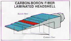
The headshell is a seven layer design. Carbon and Boron were used to make this laminate. Each laminate layer has opposing fiber directions. The result is excellent resonance cancelation.
The L-07D detachable headshell is shown above.
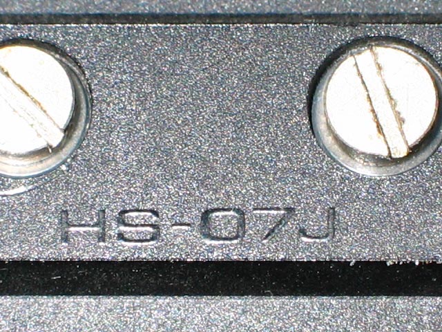
The L-07D headshell finger assembly is marked with part number HS-07J, as shown above.
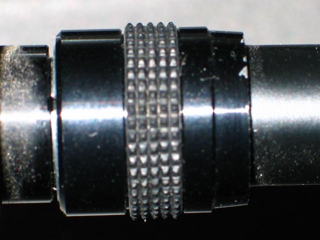
Details of the headshell mounting collar of the tonearm is seen above.
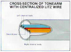
The picture above demonstrates the penta-structure of the tonearm wiring. The perfect centering of the tonearm wires minimizes capacitance of the wiring.
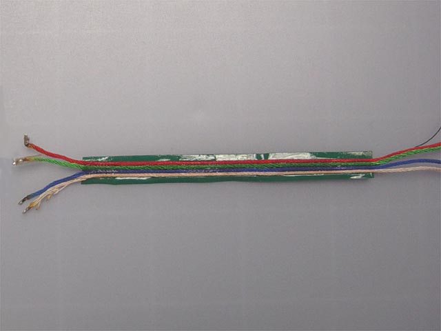
The penta-structure of the tonearm wiring is shown above.
The cross-sectional pictures above show some of the tonearm and tonearm base features described in this section.
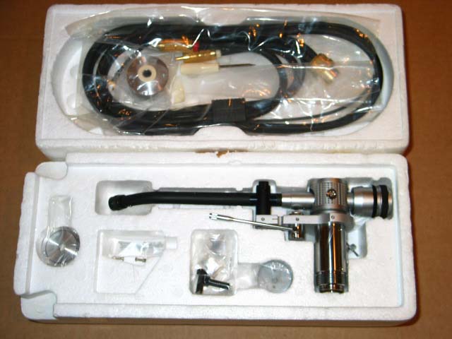
The picture above shows the L-07D tonearm in its protective styrofoam case. The picture above shows some of the the pieces included in the tonearm case. The parts originally contained in the tonearm case include: tonearm assembly , headshell and finger assembly, platter sheet lifting screws, three sets of short, medium and long cartridge mounting screws/hardware, screwdriver, tonearm cable, platter cover handle and screws, three sub-platter mounting screws, three platter cover handle mounting screws, power cord for non-U.S.A, models, grounding wire, compensating felt strips for DS-20, 45 rpm adapter/overhang gauge, tonearm sub-weight, and picture card identifying all parts.
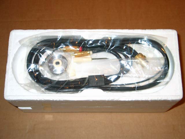
The picture above shows the top of the upper section of the tonearm case, with the tonearm cable and dust cover knob.
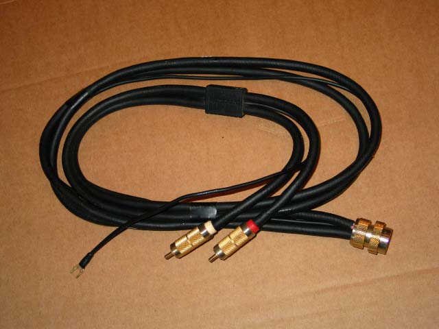
Thr L-07D tonearm cable is shown above. All connection points are heavily gold plated, including the ground wire spade end.
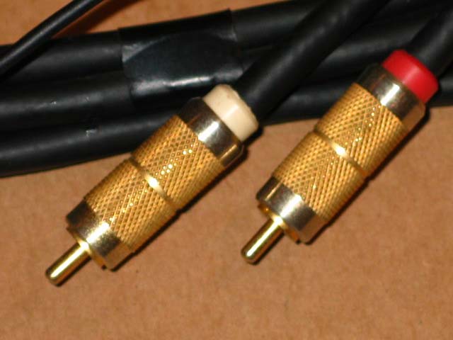
Gold plated male RCA terminations shown above.
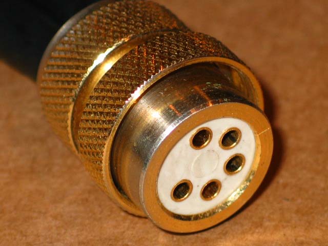
DIN connector of tonearm cable attaches to tonearm via a screw on collar for secure attachment. Note the gold plated contacts.
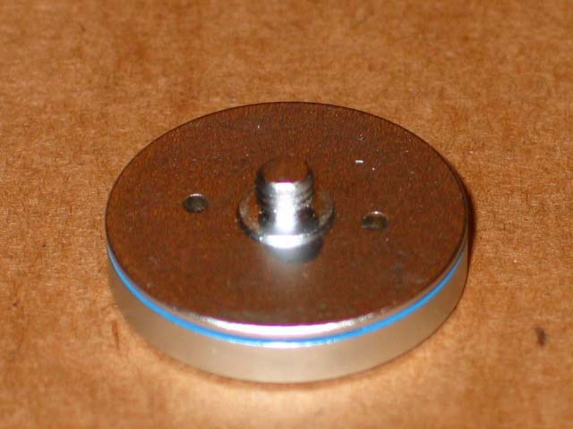
Tonearm sub-weight shown above. The sub-weight is used for cartridges weighing 9 to 22 grams. The sub-weight by itself weighs 36.0 grams. The sub-weight diameter is 29.80mm. The sub-weight disc portion thickness is 6.05mm. The threaded portion has M5.0 threads and protrudes from the body of the sub-weight. The combined thickness of the disc portion and threaded portion is 11.01mm, therefore the threaded portion protrudes 4.96mm from the surface of the disc portion.
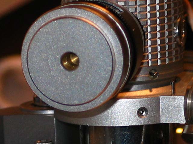
The hole in the rear of the tonearm counterweight is threaded to accept the sub-weight.
The sub-weight is shown attached to the tonearm in the photo above.
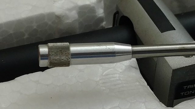
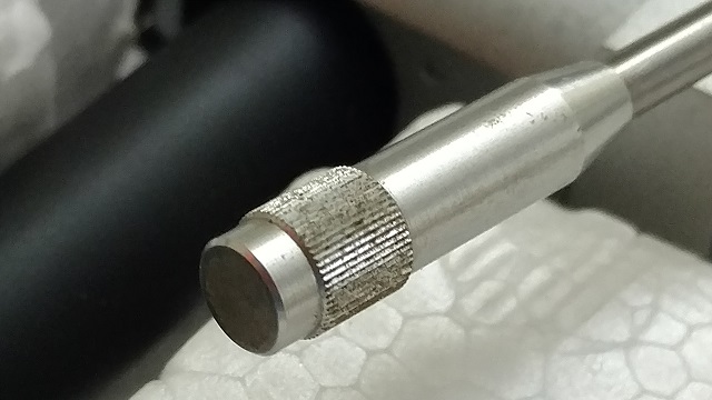
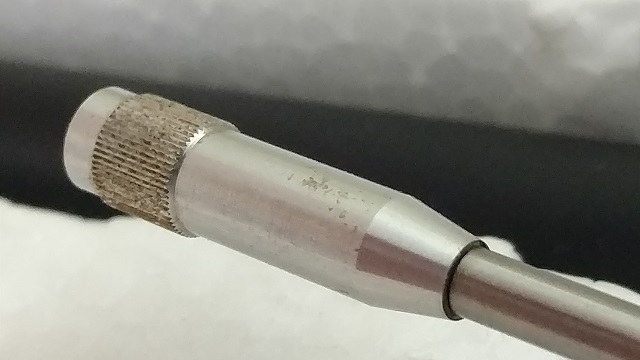
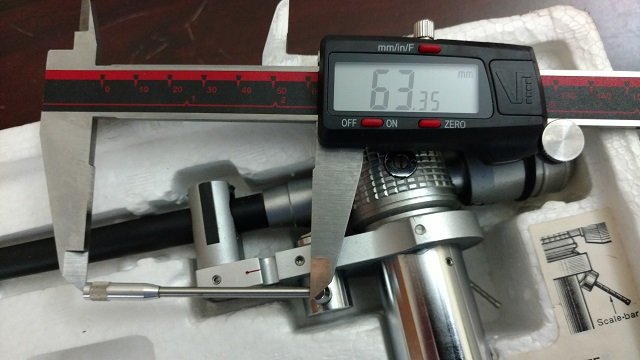
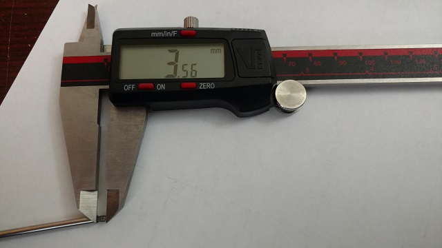
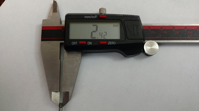
Tonearm Elevation Lever
If the Tonearm Elevation Lever is damaged and needs to be replaced, the following measurements can assist a machinist in making a replacement. The weight of the Tonearm Elevation Lever is 3.56 grams.

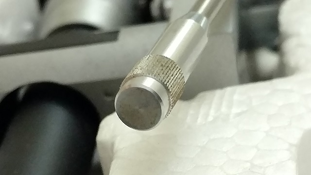
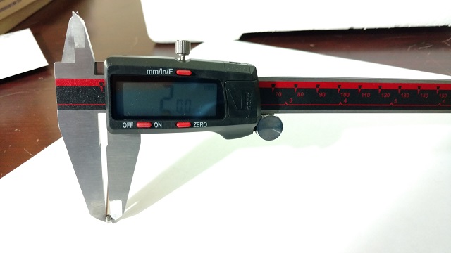
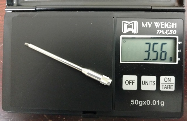
Tonearm Elevation Lever Measurements (PDF)
All trademarks and rights belong to the OEM and are reproduced here for information purposes only. Copyright © 2003-2022. All rights reserved.